Buick Enclave: Timing Gears
* PLEASE READ THIS FIRST *
NOTE: The information in this article is written as a general engine service guide. The examples, illustrations, and measuring methods may not match every specific engine layout or every production variation. They are intended to help a technician understand the basic overhaul process, including cleaning, checking, measurement, assembly, and machine shop practices commonly used during engine repair.
Before performing work on a Buick Enclave or any other vehicle, always consult the correct engine overhaul article in the ENGINES section when one is available. Factory service data should be used for torque values, sealant locations, wear limits, alignment checks, and any procedure that applies to the exact engine being repaired.
TIMING GEAR BACKLASH & RUNOUT
NOTE: Timing gear procedures can vary by engine design. The following description explains the general method used on engines where the camshaft gear meshes directly with the crankshaft gear. It is not a substitute for the dedicated engine service information for the vehicle in the bay.
Use clean measuring tools, support the engine components securely, and compare every reading with the published service limit for the application. Accurate measurement is important because small gear alignment errors can affect valve timing stability, oil seal life, and overall engine smoothness.
On engines where the camshaft gear operates directly against the crankshaft gear, both gear backlash and gear runout must be checked before final assembly. Backlash is the small amount of free movement between the meshing teeth. Too little clearance can cause gear noise, binding, and accelerated wear. Too much clearance can create timing variation, gear rattle, and uneven tooth loading.
To check timing gear backlash, install a dial indicator so the indicator tip rests firmly against a tooth on the camshaft gear. The indicator must be mounted solidly enough that it will not move while the gear is being rocked. Rotate the camshaft gear as far as possible in one direction without turning the crankshaft gear. Set the dial indicator to zero. Then rotate the camshaft gear in the opposite direction as far as possible and record the indicator reading. This reading represents the amount of backlash between the camshaft gear and crankshaft gear.
To determine timing gear runout, position the dial indicator with the tip resting against the face edge of the camshaft gear. Adjust the indicator to zero, then slowly rotate the camshaft gear through a full 360 degrees while watching the dial. The highest variation shown on the gauge indicates gear runout. During this check, the gear should rotate smoothly, and the indicator tip should remain squarely on the measured surface.
If either backlash or runout is outside the allowed range, examine the gear teeth, mounting surfaces, keyways, locating dowels, and related shafts before installing new parts. A worn camshaft gear, damaged crankshaft gear, distorted mounting face, or debris trapped behind the gear can all produce an incorrect reading. When the measurement remains beyond the service limit after cleaning and careful checking, renew the camshaft gear, crankshaft gear, or both as required by the engine service procedure.
REAR MAIN OIL SEAL INSTALLATION
NOTE: Rear main oil seal installation is a precision operation. The examples below describe common seal types and general installation practices. The actual procedure may differ depending on crankshaft design, seal housing style, block machining, and the service parts supplied for the engine.
Always use the correct rear main seal, proper installer, and recommended lubricant or sealant. A seal that is installed dry, cocked, cut, or driven too deeply can leak shortly after the engine is returned to service.
One-Piece Type Seal
For one-piece rear main oil seal installation, first look over the crankshaft sealing surface and the seal bore in the block or housing. The contact area must be clean, smooth, and free of burrs, corrosion, old sealant, or scratches that could damage the new seal. If the outside diameter of the seal is not factory coated, apply the specified sealer to the block contact surface as directed by the service procedure.
Lubricate the seal lip lightly with clean engine oil unless the seal manufacturer states otherwise. Position the seal squarely in the bore and press it into place using the proper oil seal installer. Do not drive the seal with a punch or uneven tool, because distortion of the seal case can create a leak path. The seal should seat evenly and remain aligned with the crankshaft centerline. See Fig. 27.
After installation, confirm that the lip has not rolled, folded, or been displaced from the sealing surface. On a Buick Enclave engine repair, this final visual check helps prevent a repeat oil leak that may otherwise appear only after the transmission or engine has already been reinstalled.
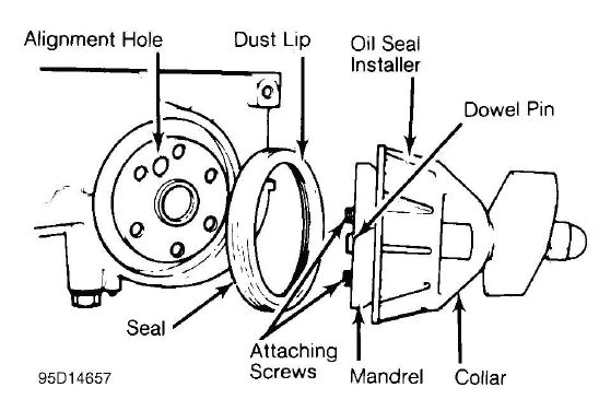
Fig. 27: Installing Typical One-Piece Oil Seal
Rope Type Seal
For rope type rear main oil seal installation, press the seal lightly into the seat area first, making sure it follows the machined groove without twisting. Use the correct seal installer to fully seat the rope seal in the bearing cap or cylinder block. The seal must be packed evenly into the groove so it can form a consistent sealing surface around the crankshaft.
Trim the seal ends even with the cylinder block parting surface or as specified by the service procedure. Use a sharp cutting tool and avoid pulling the rope material while trimming, since stretching the seal can change its fit. Some applications require sealer to be applied to the main bearing cap mating surface before installation. Apply sealant only where specified, because excess material can squeeze into unwanted areas and interfere with bearing cap seating. See Fig. 28.
Before final assembly, make sure the bearing cap fits flush and that the seal ends are not pinched out of position. A rope seal relies on uniform compression, so careful trimming and seating are just as important as the seal itself.
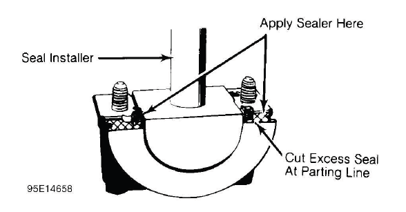
Fig. 28: Installing Typical Rope Seal
Split-Rubber Type Seal
Follow the manufacturer's procedure when installing split-rubber rear main oil seals. Installation steps can vary depending on the seal design, engine family, crankshaft surface, and whether the seal halves are installed with offset ends or aligned with the block parting line. Some split seals require a small amount of sealant at the joint area, while others must be installed clean and dry at the outside edge.
Check both seal halves before installation. The sealing lips must be clean and undamaged, and the molded ends must meet properly when the cap is installed. Lubricate the seal lip with clean engine oil where required, then position each half carefully so the lip faces the correct direction. Incorrect orientation can allow oil to pass the seal almost immediately after start-up. See Fig. 29.
Once the bearing cap is tightened, rotate the crankshaft by hand if the service procedure allows it. The crankshaft should turn smoothly without abnormal drag caused by a displaced seal. This extra step is useful on any engine build, especially where rear main seal access requires significant labor.
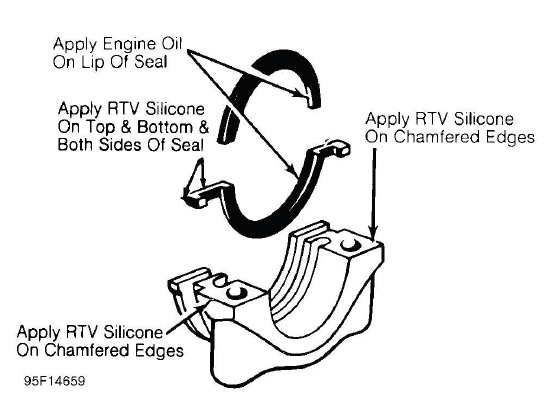
Fig. 29: Installing Typical Split-Rubber Seal
