Buick Enclave: Specifications, Diagnostic Information and Procedures
SPECIFICATIONS
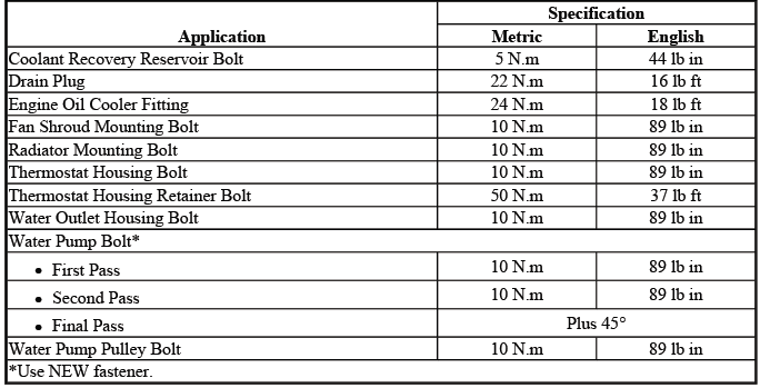
FASTENER TIGHTENING SPECIFICATIONS
Fastener Tightening Specifications
Fastener tightening specifications are provided so cooling system and related engine heating/cooling components can be secured with the correct clamping force. Proper torque is important because these parts are exposed to heat cycles, vibration, coolant pressure, electrical loads, and normal engine movement. Loose fasteners can lead to leaks, poor electrical contact, vibration, fan noise, or component movement, while overtightening can damage threads, housings, brackets, or sealing surfaces.
When servicing the Buick Enclave engine heating and cooling system, always follow the specified tightening values and use the correct sequence where a procedure requires it. Before reassembly, inspect bolts, nuts, clips, connectors, brackets, and mounting points for corrosion, distortion, broken retainers, or damaged threads that could affect the repair.
SCHEMATIC WIRING DIAGRAMS
ENGINE HEATING/COOLING WIRING SCHEMATICS
Engine Cooling
The engine cooling wiring schematics show how the cooling fan relays, fan motors, ECM control circuits, power feeds, grounds, connectors, and related wiring are arranged. These diagrams are essential when diagnosing cooling fan trouble codes because the concern may be caused by an electrical fault rather than a failed fan motor or relay.
Use the wiring schematic to confirm circuit paths before testing. A correct diagnosis depends on knowing which relay is being commanded, which circuit should have voltage, which side is controlled by the ECM, and where the ground or feedback signal is expected. On the Buick Enclave, the cooling fan system is electronically controlled, so testing should be done with a scan tool, wiring information, and proper circuit checks rather than by replacing parts based only on a code.
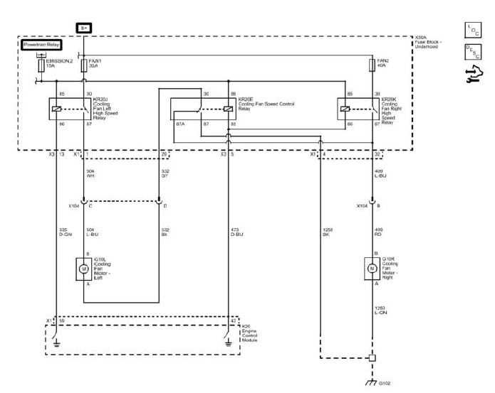
Fig. 1: Engine Cooling Wiring Schematics
DIAGNOSTIC INFORMATION AND PROCEDURES
DIAGNOSTIC CODE INDEX
The diagnostic code index is used to locate the correct procedure for a stored or current trouble code. Before beginning individual circuit testing, confirm the code, review freeze frame or failure records, and check whether other related codes are present. Multiple codes can sometimes point to a shared power feed, ground, connector, relay, or control circuit problem.
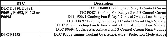
DTC P0480, P0481, P0691, P0692, P0693 OR P0694: COOLING FAN RELAY
Diagnostic Instructions
These diagnostic trouble codes relate to the cooling fan relay control circuits. The ECM monitors the commanded state of the fan relay circuits and compares it with the expected feedback condition. If the control circuit does not respond as expected, a DTC may set. Because the cooling fans are important for engine temperature control and air conditioning performance, these codes should be diagnosed carefully.
- Perform the Diagnostic System Check - Vehicle prior to using this diagnostic procedure. This helps confirm that the vehicle communication system, modules, power feeds, and basic diagnostic conditions are suitable for testing.
- Review Strategy Based Diagnosis for an overview of the diagnostic approach. A structured diagnostic process helps prevent unnecessary relay, fan motor, or ECM replacement.
- Diagnostic Procedure Instructions provides an overview of each diagnostic category. Review these instructions so circuit testing, connector inspection, and scan tool commands are interpreted correctly.
DTC Descriptors
DTC P0480
- Cooling Fan Relay 1 Control Circuit
DTC P0481
- Cooling Fan Relays 2 and 3 Control Circuit
DTC P0691
- Cooling Fan Relay 1 Control Circuit Low Voltage
DTC P0692
- Cooling Fan Relay 1 Control Circuit High Voltage
DTC P0693
- Cooling Fan Relays 2 and 3 Control Circuit Low Voltage
DTC P0694
- Cooling Fan Relays 2 and 3 Control Circuit High Voltage
Low voltage and high voltage descriptions help identify the direction of the fault. A low voltage condition may indicate a short to ground, a pulled-down circuit, or an internal relay/control issue. A high voltage condition may indicate an open circuit, a short to voltage, or a feedback signal that does not match the command. The exact cause must be confirmed by testing.
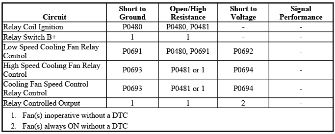
Diagnostic Fault Information
The diagnostic fault information table supports circuit-level testing by identifying the likely effect of opens, shorts to ground, shorts to voltage, and high resistance in specific circuits. Use this information together with the wiring schematic and connector end views to locate the fault without disturbing unrelated components.
Circuit/System Description
The engine cooling fan system consists of a cooling fan assembly containing two electric cooling fans. The engine control module (ECM) uses two fan control circuits and a series of three relays to command the fans ON in either high speed or low speed, depending on cooling requirements. Fan operation may be requested because of engine coolant temperature, air conditioning pressure, vehicle operating conditions, or diagnostic output commands.
The ECM activates the applicable relay by grounding the control circuit with a solid-state device called a driver. Each driver is equipped with a feedback circuit that is pulled up to a voltage. By monitoring feedback voltage, the ECM can determine whether the control circuit is open, shorted to ground, or shorted to voltage.
In low speed operation, both fans are turned ON at a reduced speed. In high speed operation, both fans are turned ON at full speed. This staged operation allows the Buick Enclave cooling system to control temperature efficiently while limiting unnecessary fan noise and electrical load when full fan speed is not required.
If the relay command, control circuit, feedback signal, or fan operation does not match what the ECM expects, one or more cooling fan relay DTCs may set. A failed relay is possible, but wiring damage, poor terminal tension, corrosion, open circuits, shorted circuits, power feed problems, ground concerns, or fan motor faults can create similar symptoms.
Conditions for Running the DTC
- The ignition voltage is greater than 11 volts. A stable voltage supply is required so the ECM can accurately command the relays and monitor the feedback circuit.
- The ECM driver transitions from ON to OFF or from OFF to ON. The diagnostic runs when the control circuit is commanded to change state.
- DTCs P0480, P0481, P0691, P0692, P0693 and P0694 run continuously when the conditions above are met.
Conditions for Setting the DTC
The commanded state of the ECM driver and the actual state of the control circuit do not match for more than 5 seconds. This means the ECM has requested one condition, but the circuit feedback indicates a different condition long enough for the module to identify a fault.
Action Taken When the DTC Sets
DTCs P0480, P0481, P0691, P0692, P0693 and P0694 are Type B DTCs. When one of these codes sets, the vehicle may store the failure information and may illuminate a warning indicator according to Type B DTC logic. Depending on the failure, cooling fan operation may be limited, forced on, or inconsistent.
Conditions for Clearing the MIL/DTC
DTCs P0480, P0481, P0691, P0692, P0693 and P0694 are Type B DTCs. The codes may clear according to the normal Type B diagnostic conditions once the fault is no longer detected, or they may be cleared with a scan tool after the repair is completed and verified.
Diagnostic Aids
- The ECM has the capability of providing command to the fan relays even when a scan tool output control is being used. Always refer to the fan control command parameters on the scan tool to know which fans are being commanded ON by the ECM. This helps avoid confusion between scan tool output control and ECM-requested fan operation.
- The scan tool cooling fan output control operates as follows:
- Cooling Fan Relay 1 operates both fans at a low speed
- Cooling Fan Relays 2 and 3 operates one fan at a high speed
- Cooling Fan Relays 1, 2 and 3 operates both fans at a high speed
When diagnosing the cooling fan system, listen for relay operation, verify actual fan movement, and compare commanded fan state with observed fan behavior. A relay click does not always prove that current is reaching the fan motor, and a fan that does not run does not automatically mean the fan motor is defective. Circuit voltage, ground integrity, connector condition, and relay output should all be checked as needed.
Reference Information
Schematic Reference
Engine Heating/Cooling Schematics
Connector End View Reference
- COMPONENT CONNECTOR END VIEWS - INDEX
- Electrical Center Identification Views
Description and Operation
Cooling Fan Description and Operation
Electrical Information Reference
- Circuit Testing
- Connector Repairs
- Testing for Intermittent Conditions and Poor Connections
- Wiring Repairs
DTC Type Reference
Powertrain Diagnostic Trouble Code (DTC) Type Definitions
Scan Tool Reference
Control Module References for scan tool information
These references should be used together during diagnosis. Cooling fan relay faults can involve wiring diagrams, connector pin identification, ECM command data, relay testing, fan motor operation, and intermittent connection checks. For the Buick Enclave, reviewing the correct connector and electrical center information can save time and prevent testing the wrong circuit.
Circuit/System Verification
1. Ignition ON. Make sure the battery is sufficiently charged and the ignition voltage is within the required range before testing the fan relay circuits.
2. Verify an audible click is heard or felt from cooling fan relays 1, 2 and 3 when commanding the cooling fans ON and OFF with a scan tool. A clear relay click confirms that the relay coil may be responding to the command, but further testing may still be required if the fans do not operate correctly.
If a click is not heard or felt at one or more of the relays
Refer to Circuit/System Testing. The control circuit, relay coil, power feed, ground, connector condition, or ECM command path may need to be checked.
If a click is heard or felt at each of the relays
3. Operate the vehicle within the Conditions for Running the DTC. You may also operate the vehicle within the conditions that you observed from the Freeze Frame/Failure Records data. This helps confirm whether the fault returns under the same electrical load, temperature, command state, or operating condition that originally caused the code to set.
If the DTC does not reset during verification, inspect for intermittent conditions such as loose relay terminals, poor connector tension, corrosion, harness movement, rubbed wiring, or a fault that appears only when the engine compartment is hot. Cooling fan circuit concerns can be intermittent, so duplicating the original conditions is often the key to an accurate repair.
4. Verify that the DTC does not set. This confirmation step is important because the cooling fan relay circuit may appear to respond during a single command, but the fault can return when the ECM commands the circuit under normal operating conditions.
If the DTC sets
Refer to Circuit/System Testing. A repeated DTC means the relay control circuit, ignition feed, relay, wiring, connector, or ECM command path still requires further diagnosis.
If the DTC does not set
5. All OK. The cooling fan relay circuit has passed the verification procedure, and no current fault is detected under the tested conditions. If the concern was intermittent, monitor the Buick Enclave under the same operating conditions described in the Freeze Frame/Failure Records data.
Circuit/System Testing
The following circuit and system tests are used to locate the cause of a cooling fan relay control DTC. Follow the sequence carefully and test all three relay circuits where specified. Skipping a relay circuit or assuming that one relay result applies to the others can lead to an incomplete diagnosis.
1. Ignition OFF, disconnect all of the cooling fan relays. Ignition ON. This prepares the relay circuits for voltage and control-side testing without the relays influencing the readings.
2. Verify that a test lamp illuminates between ground and a relay coil ignition circuit terminal listed below:
NOTE: The following tests must be performed on all three fan relay circuits.
- KR20C Cooling Fan Low Speed Relay terminal 85/2
- KR20D Cooling Fan High Speed Relay terminal 86/1
- KR20E Cooling Fan Speed Control Relay terminal 86/1
The test lamp should illuminate when the ignition circuit is capable of supplying power to the relay coil. If the lamp does not illuminate, the circuit may have an open, high resistance, a fuse issue, or another feed-side concern.
If the test lamp does not illuminate
- Ignition OFF and all vehicle systems OFF. It may take up to 2 minutes for all vehicle systems to power down. Remove the test lamp.
- Test for less than 2 ohms in the ignition circuit of the appropriate cooling fan relay, end to end.
- If 2 ohms or greater, repair the open/high resistance in the circuit. High resistance can prevent the relay coil from receiving enough current even when voltage appears present during a light-load check.
- If less than 2 ohms, verify the fuse is not open and there is voltage at the fuse. A good circuit resistance reading does not confirm fuse output unless voltage is also present at the correct point.
If the test lamp does not illuminate and the circuit fuse is open
- Ignition OFF and all vehicle systems OFF. It may take up to 2 minutes for all vehicle systems to power down. Remove the test lamp.
- Test for infinite resistance between the appropriate cooling fan relay ignition circuit and ground.
- If less than infinite resistance, repair the short to ground on the circuit. A short to ground can open the fuse repeatedly and must be corrected before installing another fuse.
- If infinite resistance test or replace the appropriate cooling fan relay. A relay with an internal fault may cause the fuse or circuit to behave incorrectly.
If the test lamp illuminates
3. Connect a DMM, set on the diode setting, between ground and a relay control circuit terminal listed below:
NOTE: The following tests must be performed on all three fan relay circuits.
- KR20C cooling fan low speed relay terminal 86/1
- KR20D cooling fan high speed relay terminal 85/2
- KR20E cooling fan speed control relay terminal 85/2
This test checks the ECM-controlled side of the relay circuit. The control circuit must respond correctly when the ECM commands the relay OFF and ON.
4. Verify the DMM reading is greater than 2.5 V or displays O.L with the cooling fan relays commanded OFF with a scan tool. This confirms that the control circuit is not being pulled low when the relay is supposed to be off.
If 2.5 V or less
- Ignition OFF, disconnect the X1 harness connector at the K20 Engine Control Module.
- Test for infinite resistance between the appropriate relay coil control circuit and ground.
- If less than infinite resistance, repair the short to ground on the circuit. A grounded control circuit can make the relay behave as though it is being commanded when it should not be.
- If infinite resistance, replace the K20 Engine Control Module. This result indicates that the external circuit does not show a short to ground, so the control fault may be internal to the module.
If greater than 2.5 V or displays O.L.
5. Verify the DMM reading is less than 1 V when commanding the cooling fan relays ON with a scan tool. When the relay is commanded on, the ECM should pull the control circuit low. If the voltage remains high, the relay command path is not completing correctly.
If greater than 1 V or displays OL.
- Ignition OFF, disconnect the X1 harness connector at the K20 Engine Control Module, ignition ON.
- Test for less than 1 V between the appropriate cooling fan relay control circuit and ground.
- If 1 V or greater, repair the short to voltage on the circuit. A control wire shorted to voltage can prevent the ECM from pulling the relay coil circuit low.
- If less than 1 V.
- Ignition OFF and all vehicle systems OFF. It may take up to 2 minutes for all vehicle systems to power down.
- Test for less than 2 ohms in the appropriate cooling fan relay control circuit end to end.
- If 2 ohms or greater, repair the open/high resistance in the circuit. An open or high-resistance control circuit can stop the relay from responding even when the ECM command is present.
- If less than 2 ohms, replace the K20 Engine Control Module. At this point, the circuit has tested correctly and the remaining fault is likely related to the control module output.
If less than 1 V
6. Test or replace the appropriate cooling fan relay. If the wiring and ECM control circuit test correctly, the relay itself may not be switching properly under load. On the Buick Enclave, relay condition should be confirmed before replacing higher-cost components.
Component Testing
Component testing verifies the electrical condition of the cooling fan relay outside of the vehicle circuit. These checks help determine whether the relay coil and internal contacts are within specification.
1. Ignition OFF.
2. Disconnect a cooling fan relay. Inspect the relay terminals and the electrical center terminals for corrosion, heat damage, looseness, or spread terminals before testing.
3. Test for 70-110 ohms between terminals 85/2 and 86/1.
If less than 70 ohms or greater than 110 ohms
Replace the cooling fan relay. A resistance reading outside this range indicates that the relay coil is not within specification.
If between 70-110 ohms
4. Test for infinite resistance between the following terminals:
- 30 and 86
- 30 and 87
- 30 and 85
- 85 and 87
OR
- 3 and 2
- 3 and 5
- 3 and 1
- 1 and 5
These checks confirm that the relay contacts are not shorted internally when the relay is not energized.
If less than infinite resistance
Replace the cooling fan relay. Internal continuity where there should be none indicates a failed relay.
If infinite resistance
5. Test for less than 2 ohms between KR20E Cooling Fan Speed Control Relay terminals 30/3 and 87A/4.
NOTE: This test only applies to the speed control relay.
If 2 ohms or greater
Replace the KR20E Cooling Fan Speed Control Relay. Excessive resistance at this contact can affect fan speed control and may cause incorrect operation under load.
If less than 2 ohms
6. Install a 10 A fused jumper wire between relay terminal 85 or 2 and 12 V. The fused jumper protects the circuit during bench-style relay activation testing.
7. Install a jumper wire between relay terminal 86 or 1 and ground. This energizes the relay coil so the switched contacts can be checked.
8. Test for less than 2 ohms between terminals 3/30 and 5/87.
If 2 ohms or greater
Replace the cooling fan relay. High contact resistance can prevent the cooling fan circuit from carrying current correctly even though the relay clicks.
If less than 2 ohms
9. All OK. The relay has passed the component test. If the DTC or fan concern remains, continue diagnosis of the related circuits, connectors, electrical center terminals, fan motors, ECM command data, and intermittent wiring conditions.
Repair Instructions
Perform the Diagnostic Repair Verification after completing the diagnostic procedure. Verification should confirm that the cooling fans operate at the commanded speeds, that the relay commands match scan tool data, and that the DTC does not reset under the required conditions.
- Relay Replacement (Within an Electrical Center) , Relay Replacement (Attached to Wire Harness)
- Control Module References for ECM replacement, setup and programming
When replacing relays, wiring, or the ECM on a Buick Enclave, make sure the repair is completed according to the appropriate service procedure. If an ECM is replaced, required setup, programming, and relearn operations must be performed before final verification.
DTC P1258: ENGINE COOLANT OVERTEMPERATURE - PROTECTION MODE ACTIVE
This diagnostic trouble code indicates that the engine coolant temperature has reached a level where the vehicle may enter a protection strategy to help reduce the risk of engine damage. If this code is present, inspect the cooling system, coolant level, radiator airflow, cooling fan operation, thermostat function, coolant leaks, water pump operation, and related temperature sensor data before returning the vehicle to service.
Diagnostic Instructions
Use this diagnostic procedure only after the basic vehicle-level checks have been completed. DTC P1258 relates to an engine coolant overtemperature condition, so the diagnosis should not focus on one component too quickly. Cooling fan operation, coolant level, airflow through the radiator, temperature sensor data, thermostat operation, and general cooling system condition all need to be considered before the vehicle is returned to service.
- Perform the Diagnostic System Check - Vehicle prior to using this diagnostic procedure. This confirms that the vehicle modules, communication system, warning indicators, and basic diagnostic functions are operating correctly.
- Review Strategy Based Diagnosis for an overview of the diagnostic approach. A structured process helps avoid replacing parts unnecessarily and helps identify whether the concern is electrical, mechanical, coolant-related, airflow-related, or intermittent.
- Diagnostic Procedure Instructions provides an overview of each diagnostic category. Review these instructions before testing so scan tool data, circuit checks, symptom checks, and repair verification are interpreted correctly.
DTC Descriptors
DTC P1258
- Engine Coolant Overtemperature - Protection Mode Active
Circuit/System Description
The engine control module (ECM) uses the engine coolant temperature sensor to monitor the engine for an overtemperature condition. This condition occurs when the coolant temperature rises above a calibrated value. The ECM continuously evaluates temperature information so it can protect the engine when cooling system performance is no longer sufficient.
When an overtemperature condition is detected, the ECM can place the engine into a protection strategy. The ECM will alternately disable 2 groups of cylinders by turning OFF the fuel injectors. By switching between the 2 groups of cylinders, the ECM is able to reduce heat production and help lower coolant temperature.
This protection mode is not a normal operating condition. It is a response to excessive engine temperature and should be treated seriously. If the Buick Enclave enters this mode, the cause of the overheating must be found before normal operation is assumed safe.
Conditions for Running the DTC
- The engine is operating for greater than 30 seconds.
- DTC P1258 runs continuously once the conditions above have been met.
Because the DTC runs continuously after the engine has been operating long enough, the ECM can detect an overheating condition quickly if coolant temperature rises beyond the calibrated threshold.
Conditions for Setting the DTC
The ECM detects that engine coolant temperature is warmer than 132ºC (270ºF) for 2 seconds or greater. This indicates a severe temperature condition, not a minor fluctuation. At this point, the cooling system should be inspected carefully before further driving.
Action Taken When the DTC Sets
- DTC P1258 is a Type A DTC.
- The engine will operate in the Overheated Engine Protection Operating Mode.
- The IP will illuminate the coolant temperature indicator lamp and the driver information center (DIC), if equipped, may display a message.
- If the protection mode is active and an ECT sensor DTC sets, the protection mode will remain active at the start of the next drive cycle until the ECT sensor DTC runs and passes.
When this code sets, the driver may notice reduced engine performance, warning indicators, or a message on the display. These reactions are designed to protect the engine from damage caused by excessive heat. Continued operation during an overheating event can lead to serious engine damage, coolant loss, gasket failure, or other costly repairs.
Conditions for Clearing the MIL/DTC
DTC P1258 is a Type A DTC. The code should only be cleared after the overheating cause has been identified, repaired, and verified. Clearing the code without correcting the root cause can allow the same overtemperature condition to return.
Reference Information
Schematic Reference
Engine Controls Schematics
Connector End View Reference
COMPONENT CONNECTOR END VIEWS - INDEX
Description and Operation
- Cooling Fan Description and Operation
- Instrument Cluster Description and Operation
- Indicator/Warning Message Description and Operation
DTC Type Reference
Powertrain Diagnostic Trouble Code (DTC) Type Definitions
Scan Tool Reference
K20 Engine Control Module: Scan Tool Information (LLT) for scan tool information
The reference information should be used together. Engine coolant overtemperature diagnosis may require scan tool temperature data, cooling fan command information, wiring checks, warning message operation, and a review of cooling system mechanical function. On the Buick Enclave, overheating should never be diagnosed from the code alone without checking the supporting data.
Circuit/System Verification
1. Ignition ON. Confirm that the scan tool communicates normally and that the vehicle voltage is suitable for testing.
2. Verify DTC P0480, P0481, P0691, P0692, P0693 or P0694 is not set. These codes relate to cooling fan relay control circuits and can directly affect fan operation.
If a DTC is set
Refer to DTC P0480, P0481, P0691, P0692, P0693 or P0694. Cooling fan relay faults must be diagnosed first because an inoperative or improperly controlled fan can cause the engine to overheat.
If no DTCs is set
3. Verify the cooling fan operates at each available speed as commanded with a scan tool. The fan should respond to the commanded low and high speed requests according to system design.
NOTE: A short delay occurs before the ECM changes the cooling fan speed.
Cooling fan does not operate
Refer to Cooling Fan Inoperative. A fan that does not run can quickly allow coolant temperature to rise, especially at idle, in traffic, during high ambient temperatures, or when the air conditioning system is operating.
Cooling fan operates
4. Verify that the engine does not overheat. Monitor actual coolant temperature with a scan tool and compare it with the instrument panel indication. Also observe whether the temperature rises only at idle, only during driving, during A/C operation, or under load.
Engine overheats
Refer to Engine Overheating. The cause may involve coolant level, air trapped in the system, thermostat operation, radiator flow, water pump performance, fan airflow, leaks, restrictions, or incorrect coolant mixture.
Engine does not overheat
5. Operate the vehicle within the Conditions for Running the DTC. If possible, duplicate the conditions shown in Freeze Frame/Failure Records data, such as engine speed, vehicle speed, coolant temperature, ambient temperature, and load.
If the DTC sets
Refer to Symptoms - Engine Cooling. A recurring P1258 means the overheating condition or temperature-related input still needs diagnosis.
If the DTC does not set
6. All OK. The Buick Enclave has passed the verification under the tested conditions. If the original concern was intermittent, continue to inspect for loose connectors, low coolant level, restricted airflow, intermittent fan operation, or conditions that appear only during extended driving.
Repair Instructions
Perform the Diagnostic Repair Verification after completing the diagnostic procedure. Verification should confirm that the cooling fans operate correctly, the engine reaches normal operating temperature without overheating, no related DTCs return, and the warning indicator or DIC message does not reappear.
SYMPTOMS - ENGINE COOLING
Important Preliminary Inspections Before Starting
Before using Symptom diagnosis, perform the following. These preliminary inspections are important because many cooling system concerns can be found before advanced testing begins. A low coolant level, dirty radiator, poor electrical ground, or blocked condenser can create symptoms that look like a more complicated fault.
- Perform Diagnostic System Check - Vehicle and verify all of the
following items:
- Engine control module (ECM) and malfunction indicator lamp (MIL) are operating correctly.
- There are no diagnostic trouble codes (DTCs) stored.
- Scan tool data is within a normal operating range.
- Verify the customer concern. Ask when the overheating occurs, whether the vehicle was in traffic or on the highway, whether the air conditioning was on, whether coolant was added recently, and whether any warning message appeared.
- Perform the Visual/Physical Inspection in this section. The visual/physical inspection is extremely important and can lead to correcting a condition without additional testing. It may also help reveal the cause of an intermittent condition.
- Locate the correct symptom. Perform the tests and inspections associated with the symptom. A vehicle that overheats only at idle may require a different diagnostic path than one that overheats only under load or at highway speed.
Review the entire cooling system operation in order to become familiar with the system functions. Refer to Cooling Fan Description and Operation and Cooling System Description and Operation. Understanding how coolant flow, radiator heat transfer, thermostat operation, pressure control, airflow, and fan strategy work together is essential for an accurate diagnosis.
Visual/Physical Inspection
CAUTION: Use the connector test adapter kit EL-35616-F for any test that requires probing the following items:
- The control module harness connectors
- The electrical center fuse/relay cavities
- The component terminals
- The component harness connector
Using this kit will prevent damage caused by the improper probing of connector terminals.
Several of the symptom procedures call for a careful visual and physical inspection. This can lead to correcting a condition without further tests and can save time. The inspection should be detailed, because cooling system symptoms may be caused by visible damage, poor connections, leaks, airflow restrictions, or incorrect prior repairs.
- Ensure that the control module grounds are clean, tight and correctly located. Poor grounds can affect ECM operation, cooling fan control, sensor readings, and diagnostic accuracy.
- Inspect cooling system hoses and pipes for splits, kinks and improper connections. Inspect thoroughly for any type of leak or restriction. A collapsed hose, restricted pipe, loose clamp, or seepage mark can point directly to the cause of overheating.
- Inspect for a dirty or restricted radiator or HVAC condenser. Debris, mud, leaves, bent fins, or blockage between the condenser and radiator can reduce airflow and cause temperature rise, especially at low speed.
- Inspect for aftermarket devices which could affect the operation of the cooling system. Added grille covers, auxiliary lights, incorrect fans, wiring modifications, or non-OEM parts may reduce airflow or interfere with fan control.
- Inspect the easily accessible or visible system components for obvious damage or conditions which could cause the symptom. This includes fan blades, shrouds, wiring, connectors, coolant residue, damaged brackets, loose components, or signs of impact damage.
- Inspect the coolant recovery reservoir for proper coolant level. On the Buick Enclave, low coolant level can allow air pockets, poor heater performance, overheating, or inconsistent temperature readings.
After the visual inspection, correct any obvious condition before continuing with more detailed tests. A simple issue such as a loose connector, low coolant level, blocked radiator face, or damaged hose can trigger symptoms that appear much more serious than they are.
Identifying Intermittent Conditions
Many intermittent conditions occur when a wiring harness, connector, relay, sensor, or related component moves because of engine torque, rough pavement, vibration, heat expansion, or normal physical movement of the vehicle. These concerns can be difficult to duplicate because the circuit may test correctly while the vehicle is stationary, then fail only when the engine compartment is hot, the vehicle is driven over bumps, or the harness shifts under load.
When diagnosing an intermittent cooling system or cooling fan concern on a Buick Enclave, avoid replacing parts too quickly. A poor terminal connection, moisture in a connector, or a harness that rubs against a bracket can create symptoms that appear and disappear. Refer to the following list to help isolate an intermittent condition:
- Water intrusion in connectors, terminals or components. Moisture can cause corrosion, temporary shorts, incorrect sensor readings, or relay control faults.
- Poor connector mating. A connector that is not fully seated may lose contact as vibration or heat changes the position of the harness.
- Terminal contact. Loose, spread, backed-out, or damaged terminals can interrupt current flow even when the connector appears connected from the outside.
- High circuit or component resistance-High resistance can include any resistance, regardless of the amount, which can interrupt the operation of the component. Even a small resistance increase can affect fan relay control, sensor feedback, or ECM command accuracy when the circuit is under load.
- Harness' that are routed too tight or chaffed circuits. A harness under tension can pull on connector terminals, while chafed insulation can allow intermittent shorts to ground or voltage.
- High or low ambient temperatures. Temperature changes can make a marginal connection expand, contract, or fail only under certain weather conditions.
- High or low engine coolant temperatures. Some concerns appear only when the engine reaches operating temperature or when the cooling fan strategy changes.
- High underhood temperatures. Heat can increase resistance, soften wiring insulation, and affect relays or sensors that are already weak.
- Heat build up in components or circuits due to circuit resistance, poor terminal contact or high electrical load. This can create a cycle where resistance causes heat, and heat makes the connection worse.
- High or low system voltage. Incorrect voltage can affect relay operation, ECM control circuits, fan speed, and sensor values.
- High vehicle load conditions. Towing, steep grades, heavy traffic, A/C use, or extended idling can make a weak cooling system problem more noticeable.
- Rough road surface. Bumps can move harnesses, relays, connectors, and fan assemblies enough to reveal an intermittent connection.
- Electro-magnetic interference (EMI)/circuit interference from relays, solenoids or other electrical surge. Electrical noise or voltage spikes can interfere with sensitive control circuits.
- Incorrect installation of non-factory, aftermarket or after factory add on accessories. Added wiring, lighting, fan controls, alarm systems, remote starters, or other electrical equipment may affect cooling fan control or sensor circuits if installed incorrectly.
If an intermittent fault is detected, refer to Testing for Intermittent Conditions and Poor Connections for specific strategies in diagnosing intermittent conditions. This type of testing may include moving the harness while monitoring scan tool data, checking terminal tension, inspecting connector seals, testing voltage drop under load, and duplicating the same conditions reported by the customer.
Symptom List
Refer to a symptom diagnostic procedure from the following list in order to diagnose the symptom. Selecting the correct symptom path is important because cooling system complaints can be caused by mechanical, electrical, airflow, coolant-flow, sensor, or control module concerns.
- Cooling Fan Always On
- Cooling Fan Inoperative
- Engine Overheating
- Loss of Coolant
- Thermostat Diagnosis
- Engine Fails To Reach Normal Operating Temperature
For the Buick Enclave, the actual symptom should be verified before testing begins. A fan that runs constantly is not diagnosed the same way as a fan that never turns on, and an overheating condition at idle may have a different cause than overheating at highway speed.
COOLING FAN ALWAYS ON
Diagnostic Instructions
This diagnostic procedure is used when the cooling fans continue to operate when they should not be commanded on. A fan that stays on can be caused by a valid ECM command, a sensor input that is skewed, a relay stuck closed, a short to voltage, a control circuit fault, or an aftermarket electrical issue. Confirming whether the ECM is commanding the fans is the first step.
- Perform the Diagnostic System Check - Vehicle prior to using this diagnostic procedure. This confirms that the vehicle’s diagnostic system is communicating correctly and that no larger system issue is being overlooked.
- Review Strategy Based Diagnosis for an overview of the diagnostic approach. A logical diagnostic process helps separate a real cooling demand from an electrical fault.
- Diagnostic Procedure Instructions provides an overview of each diagnostic category. These instructions help clarify when to use scan tool data, circuit testing, component testing, and visual inspection.
Circuit/System Description
The engine cooling fan system consists of a cooling fan assembly containing two electric cooling fans. The engine control module (ECM) uses two fan control circuits and a series of three relays to command the fans ON in either high speed or low speed, depending on cooling requirements. Cooling fan operation may be requested because of engine coolant temperature, air conditioning pressure, underhood heat, diagnostic output control, or other operating conditions.
The ECM activates the applicable relay by grounding the control circuit with a solid-state device called a driver. Each driver is equipped with a feedback circuit that is pulled up to a voltage. By monitoring this feedback voltage, the ECM can determine whether the control circuit is open, shorted to ground, or shorted to voltage.
In low speed operation, both fans are turned ON at a reduced speed. In high speed operation, both fans are turned ON at full speed. This staged operation allows the cooling system to manage temperature and air conditioning performance while limiting unnecessary fan noise and electrical load when maximum airflow is not required.
If the fans remain on when scan tool data shows no fan command, the concern is likely not a normal ECM request. In that case, the fault may be in a relay contact, relay output circuit, fan motor circuit, electrical center terminal, or a short to voltage. If scan tool data shows the ECM is commanding the fans on, sensor inputs and operating conditions must be evaluated first.
Diagnostic Aids
- The scan tool cooling fan output control operates as follows:
- Cooling Fan Relay 1 operates both fans at a low speed
- Cooling Fan Relays 2 and 3 operates one fan at a high speed
- Cooling Fan Relays 1, 2 and 3 operates both fans at a high speed
- Certain resistance conditions with IAT or ECT sensors may cause unwarranted cooling fan activation. If the ECM is commanding the cooling fans ON for no apparent reason and without any component or system DTCs set, the IAT or ECT sensor may be skewed. If this condition is suspected, refer to the temperature versus resistance tables in the appropriate Engine Controls subsection.
A skewed sensor may still produce a signal that appears believable enough not to set a DTC, yet it may indicate a temperature higher than actual. This can cause the ECM to command fan operation even though the engine is not truly overheating. Compare IAT, ECT, ambient conditions, and actual engine temperature to determine whether the data makes sense.
Reference Information
Schematic Reference
Engine Heating/Cooling Schematics
Connector End View Reference
- COMPONENT CONNECTOR END VIEWS - INDEX
- Electrical Center Identification Views
Description and Operation
Cooling Fan Description and Operation
Electrical Information Reference
- Circuit Testing
- Connector Repairs
- Testing for Intermittent Conditions and Poor Connections
- Wiring Repairs
Scan Tool Reference
Control Module References for scan tool information
Use these references together when diagnosing a fan-always-on condition. The wiring schematic helps identify relay feed, control, and output circuits; connector end views help prevent testing the wrong terminal; and scan tool data shows whether the ECM is requesting fan operation. On the Buick Enclave, this combined approach is more reliable than testing only the relay or only the fan motor.
Circuit/System Verification
1. Ignition ON. Confirm that battery voltage is stable and that the scan tool communicates with the ECM before evaluating cooling fan commands.
2. Verify that DTC P0480, P0481, P0691, P0692, P0693 or P0694 is not set. These DTCs indicate cooling fan relay control circuit faults and should be addressed before diagnosing a fan-always-on symptom as a separate concern.
If a DTC is set
Refer to DTC P0480, P0481, P0691, P0692, P0693 or P0694. A relay control DTC may explain why the cooling fans are operating incorrectly.
If no DTC is set
3. Verify the scan tool parameters listed below display OFF:
- Cooling Fan Relay 1 Command
- Cooling Fan Relays 2 and 3 Command
These parameters show whether the ECM is commanding cooling fan operation. If either parameter displays ON, the fans may be operating because the ECM believes cooling is needed, or because a sensor input is causing an unnecessary command.
If a scan tool parameter displays ON
Refer to Diagnostic Aids and Symptoms - Engine Cooling for further diagnosis. Check for skewed ECT or IAT sensor values, high A/C pressure, overheating conditions, or other inputs that could cause the ECM to request fan operation.
If both scan tool parameters display OFF
4. Verify that the fans are not activated. If the ECM command is OFF but one or both fans continue to run, the fault is likely in the relay contacts, relay controlled output circuit, electrical center, or fan power circuit.
If a fan is operating
Refer to Circuit/System Testing. The fan is operating without a commanded request, so the circuit must be checked for a stuck relay or an unwanted voltage feed.
If both fans are OFF
5. All OK. The cooling fans are not being commanded on and are not operating unexpectedly under the tested conditions. If the customer concern is intermittent, road test or heat-soak the Buick Enclave under the conditions reported by the customer and continue monitoring fan commands and sensor data.
Circuit/System Testing
Both Cooling Fans Always ON
This test is used when both cooling fans continue to run even though fan command data does not support normal fan operation. The goal is to determine whether the low speed relay, controlled output circuit, or related wiring is providing power when it should not.
1. Ignition OFF, disconnect KR20C Cooling Fan Low Speed Relay, ignition ON. Removing the relay separates the relay from the circuit so fan behavior can be evaluated without relay control influence.
2. Verify that both cooling fans are OFF. If both fans stop when the relay is removed, the relay or its control path may be involved. If the fans continue to run, voltage may be reaching the fan circuit from another source.
If the cooling fans are ON
- Ignition OFF, disconnect the harness connector at the G10R Cooling Fan Motor-Right, ignition ON. This isolates the right fan motor circuit for further voltage testing.
- Test for less than 1 V between KR20C Cooling Fan Low Speed Relay
terminal 87/5 and ground.
- If 1 V or greater, repair the short to voltage in the relay controlled output circuit. A voltage reading at this point means the circuit is being powered when it should not be, which can keep the cooling fans running unexpectedly.
If the cooling fans are OFF
3. Test or replace the KR20C Cooling Fan Low Speed Relay. If both fans stop after the relay is disconnected and no unwanted voltage is found on the controlled output circuit, the relay may be sticking internally or failing to open correctly. Inspect the relay terminals and the electrical center cavity before installing a replacement, because poor terminal tension or heat damage can also create repeat concerns.
One Cooling Fan Always ON
This test applies when only one cooling fan continues to operate when it should be off. The concern may be caused by a stuck high-speed relay, a short to voltage in the controlled output circuit, or a fan circuit that is being powered from an unintended source.
1. Ignition OFF, disconnect the KR20D Cooling Fan High Speed Relay, ignition ON. Removing the high-speed relay helps determine whether the relay is responsible for keeping the fan energized.
2. Verify the cooling fan is OFF. If the fan stops, the relay or its control path becomes the primary suspect. If the fan continues to run, the controlled output circuit must be checked for unwanted voltage.
If the cooling fan is ON
- Ignition OFF, disconnect the harness connector at the G10L Cooling Fan Motor-Left, ignition ON. This isolates the left cooling fan motor circuit so voltage can be tested without the motor affecting the result.
- Test for less than 1 V between KR20D Cooling Fan High Speed Relay
terminal 30/3 and ground.
- If 1 V or greater, repair the short to voltage in the relay controlled output circuit. Voltage on this circuit when the relay is removed indicates that the fan is receiving power from an unintended source.
If the cooling fan is OFF
3. Test or replace the KR20D Cooling Fan High Speed Relay. On the Buick Enclave, a relay that clicks normally may still have contacts that stick closed or carry voltage when they should be open, so component testing is important before final diagnosis.
Component Testing
Component testing checks the cooling fan relay outside of normal circuit operation. These tests help confirm whether the relay coil, internal contacts, and switching function are within specification. Before testing, inspect the relay case and terminals for melting, corrosion, looseness, discoloration, or signs of overheating.
1. Ignition OFF.
2. Disconnect a KR20 Cooling Fan Relay. Keep track of relay position so each relay can be tested and reinstalled or replaced correctly.
3. Test for 70-110 ohms between terminals 85/2 and 86/1. This checks the relay coil resistance.
If less than 70 ohms or greater than 110 ohms
Replace the KR20 cooling fan relay. A coil outside the specified resistance range can cause improper relay operation, no operation, or excessive current draw.
If between 70-110 ohms
4. Test for infinite resistance between the following terminals:
- 30/3 and 86/1
- 30/3 and 87/5
- 30/3 and 85/2
- 85/2 and 87/5
These checks confirm that the relay contacts and coil circuits are not shorted together when the relay is not energized.
If less than infinite resistance
Replace the KR20 Cooling Fan Relay. Continuity where none should exist indicates an internal relay fault.
If infinite resistance
5. Test for less than 2 ohms between KR20E Cooling Fan Speed Control Relay terminals 30/3 and 87A/4.
NOTE: This test only applies to the speed control relay.
If 2 ohms or greater
Replace the KR20E Cooling Fan Speed Control Relay. Excessive resistance across this contact can affect fan speed control and may cause incorrect cooling fan operation under load.
If less than 2 ohms
6. Install a 10 A fused jumper wire between relay terminal 85 or 2 and 12 V. The fused jumper provides a protected power feed while energizing the relay for testing.
7. Install a jumper wire between relay terminal 86 or 1 and ground. This energizes the relay coil so the switched contact can be checked.
8. Test for less than 2 ohms between terminals 30/3 and 87/5. This verifies that the relay can close properly and carry current through the switched contact.
If 2 ohms or greater
Replace the KR20 Cooling Fan Relay. High resistance across the closed contact can prevent proper fan operation even if the relay appears to activate.
If less than 2 ohms
9. All OK. The relay has passed the component tests. If the fan concern remains, continue diagnosis of the relay socket, wiring, fan motor circuits, electrical center terminals, ECM command data, and intermittent connection conditions.
Repair Instructions
Perform the Diagnostic Repair Verification after completing the diagnostic procedure. Verification should confirm that the cooling fans remain off when not commanded, turn on only when requested, and operate correctly at the proper speeds. If the concern was intermittent, the Buick Enclave should be checked under similar conditions to those described by the customer.
Relay Replacement (Within an Electrical Center) , Relay Replacement (Attached to Wire Harness)
COOLING FAN INOPERATIVE
Diagnostic Instructions
This diagnostic procedure is used when one or both cooling fans do not operate when commanded. A cooling fan inoperative condition can lead to poor air conditioning performance, rising engine coolant temperature at idle, overheating in traffic, or stored fan relay control DTCs. Diagnosis should confirm whether the concern is caused by a power feed, ground, relay, fan motor, wiring, connector, or ECM control issue.
- Perform the Diagnostic System Check - Vehicle prior to using this diagnostic procedure. This confirms that the diagnostic system is functioning and that no broader electrical or communication issue is affecting the test results.
- Review Strategy Based Diagnosis for an overview of the diagnostic approach. A step-by-step approach helps avoid unnecessary replacement of the fan assembly, relays, or control module.
- Diagnostic Procedure Instructions provides an overview of each diagnostic category. Review these instructions before testing so scan tool commands, circuit checks, and component tests are performed correctly.
Circuit/System Description
The engine cooling fan system consists of a cooling fan assembly containing two electric cooling fans. The engine control module (ECM) uses two fan control circuits and a series of three relays to command the fans ON in either high speed or low speed, depending on cooling requirements. Fan operation may be requested because of coolant temperature, air conditioning system pressure, engine load, or scan tool output control.
In low speed operation, both fans are turned ON at a reduced speed. In high speed operation, both fans are turned ON at full speed. This allows the cooling system to increase airflow through the radiator and condenser when additional heat removal is needed.
For the Buick Enclave, correct cooling fan operation is important not only for engine temperature control, but also for stable air conditioning performance at low vehicle speeds. If the fans fail to operate, the engine may run hot while idling or during stop-and-go driving, even if it appears normal at highway speed.
Diagnostic Aids
- The scan tool cooling fan output control operates as follows:
- Cooling Fan Relay 1 operates both fans at a low speed
- Cooling Fan Relays 2 and 3 operates one fan at a high speed
- Cooling Fan Relays 1, 2 and 3 operates both fans at a high speed
When using the scan tool, compare the commanded fan state with actual fan operation. A relay click does not prove the fan is receiving power, and a fan that does not move is not automatically defective. Power supply, ground, relay output, connector condition, and motor resistance should all be considered.
Reference Information
Schematic Reference
Engine Heating/Cooling Schematics
Connector End View Reference
- COMPONENT CONNECTOR END VIEWS - INDEX
- Electrical Center Identification Views
Description and Operation
Cooling Fan Description and Operation
Electrical Information Reference
- Circuit Testing
- Connector Repairs
- Testing for Intermittent Conditions and Poor Connections
- Wiring Repairs
Scan Tool Reference
Control Module References for scan tool information
These references should be used together to identify the proper relay cavities, circuit terminals, connector views, and scan tool parameters. Cooling fan diagnosis is most accurate when wiring information is matched with live scan tool commands and physical circuit testing.
Circuit/System Verification
1. Ignition ON. Verify that the battery voltage is stable and that the scan tool communicates with the ECM before commanding the cooling fans.
2. Verify that DTC P0480, P0481, P0691, P0692, P0693 or P0694 is not set. These DTCs identify cooling fan relay control circuit problems and should be diagnosed before continuing with a general fan-inoperative symptom check.
If a DTC is set
Refer to DTC P0480, P0481, P0691, P0692, P0693 or P0694. A relay control fault may explain why the cooling fans do not respond correctly.
If no DTCs is set
3. Verify that both cooling fans turn ON and OFF and operate at low and high speed, when commanding the appropriate cooling fan relays ON and OFF with a scan tool. Allow for normal command delay and observe whether one fan, both fans, low speed, or high speed is affected.
If a cooling fan does not operate
Refer to Circuit/System Testing. The fault may be in the B+ feed, relay, output circuit, fan motor, connector, or ground path.
If both cooling fans operate
4. All OK. The fans operated correctly during the commanded test. If the original complaint is intermittent, test the Buick Enclave under similar heat, road, idle, and A/C conditions that were present when the concern occurred.
Circuit/System Testing
The following circuit tests check whether the cooling fan relays are receiving the proper B+ feeds. A missing feed, open circuit, high resistance, or fuse concern can prevent one or both fans from operating even when the ECM command is correct.
1. Ignition OFF, disconnect all of the KR20 Cooling Fan Relays. Removing all relays allows the B+ circuits to be checked directly at the relay cavities.
2. Ignition ON, verify a test lamp illuminates between ground and the B+ circuit terminals listed below:
- KR20C Cooling Fan Low Speed Relay B+ circuit terminal 85/1
- KR20C Cooling Fan Low Speed Relay B+ circuit terminal 30/3
- KR20D Cooling Fan High Speed Relay B+ circuit terminal 87/5
- KR20D Cooling Fan High Speed Relay B+ circuit terminal 86/2
- KR20E Cooling Fan Speed Control Relay B+ circuit terminal 86/2
The test lamp should illuminate at each listed B+ terminal. A lamp that does not illuminate indicates that the relay circuit may not be receiving the required power feed.
If the test lamp does not illuminate and the circuit fuse is good
- Disconnect the appropriate cooling fan fuse or power source. This isolates the circuit so resistance can be measured accurately.
- Test for less than 2 ohms between the fuse and the appropriate relay B+
circuit terminal, end to
end.
- If 2 ohms or greater, repair the open/high resistance in the B+ circuit. High resistance can prevent the fan relay from supplying enough current under load.
- If less than 2 ohms, verify the fuse is not open and there is voltage at the fuse. A good wire test does not confirm that the fuse is supplying voltage.
If the test lamp does not illuminate and the circuit fuse is open
- Connect a DMM to the appropriate relay B+ circuit terminal. Use the meter to check whether the circuit is shorted to ground before another fuse is installed. Replacing a fuse without finding the cause can allow the fuse to open again as soon as the circuit is loaded.
- Test for infinite resistance between the B+ circuit and ground.
- If less than infinite resistance, repair the short to ground on the B+ circuit. Inspect the harness for rubbed insulation, melted wiring, trapped wires, corrosion inside connectors, or contact with metal brackets near the fan assembly and electrical center.
- If infinite resistance
- Disconnect the harness connector at the appropriate G10 Cooling Fan Motor. This isolates the fan motor from the relay output circuit so the wiring and motor can be evaluated separately.
- Test for infinite resistance between the appropriate relay controlled
output circuit terminal and
ground.
- KR20C Cooling Fan Low Speed Relay output circuit terminal 87/5
- KR20D Cooling Fan High Speed Relay output circuit terminal 30/3
- KR20E Cooling Fan Speed Control Relay circuit terminal 30/3
- If less than infinite resistance, repair the short to ground on the circuit. A grounded output circuit can prevent the cooling fans from operating and may also open the circuit fuse.
- If infinite resistance, test or replace the appropriate G10 Cooling Fan Motor. If the wiring is not shorted, the fan motor may be internally shorted, seized, or drawing excessive current.
If the test lamp illuminates
3. Connect a DMM, set on the diode setting, between ground and a relay control circuit terminal listed below:
NOTE: The following tests must be performed on both fan relay circuits.
- KR20D Cooling Fan High Speed Relay terminal 85/2
- KR20E Cooling Fan Speed Control Relay terminal 85/2
This step checks the ECM-controlled relay circuit. The control side must be able to pull low when commanded, otherwise the cooling fan relay may not energize even when the scan tool shows an ON command.
4. Verify the DMM reading is less than 1 V when commanding the cooling fan relays ON with a scan tool. A reading below 1 V indicates that the control circuit is being pulled low as expected. If the voltage remains high or the meter displays OL, the relay control path is not completing correctly.
If greater than 1 V or displays OL.
- Ignition OFF, disconnect the X1 harness connector at the K20 Engine Control Module, ignition ON. This separates the ECM from the circuit so the wiring can be checked for an unwanted voltage source.
- Test for less than 1 V between the appropriate cooling fan relay control
circuit and ground.
- If 1 V or greater, repair the short to voltage on the circuit. A control circuit shorted to voltage can prevent the ECM from grounding the relay properly.
- If less than 1 V.
- Ignition OFF and all vehicle systems OFF. It may take up to 2 minutes for all vehicle systems to power down. Allowing the modules to power down helps prevent false readings during resistance testing.
- Test for less than 2 ohms between the KR20E Cooling Fan Speed Control
Relay terminal 85 and
KR20D Cooling Fan High Speed Relay terminal 85.
- If 2 ohms or greater, repair the open/high resistance in the circuit. High resistance between these control points can prevent the high-speed fan strategy from operating correctly.
- If less than 2 ohms, replace the K20 Engine Control Module. At this stage, the external circuit has tested correctly and the fault may be within the module driver.
If less than 1 V
5. Ignition OFF and all vehicle systems OFF, disconnect the harness connector at the G10L Cooling Fan Motor - Left. It may take up to 2 minutes for all vehicle systems to power down. This prepares the left fan motor ground and related circuits for resistance testing without module or motor activity affecting the results.
6. Test for less than 5 ohms between the circuits listed below and ground:
- G10L Cooling Fan Motor - Left terminal A
- KR20E Cooling Fan Speed Control Relay terminal 87/5
A low resistance path to ground is necessary for proper cooling fan operation. Poor ground integrity can make the fan run slowly, fail to start, operate intermittently, or place extra load on the relay circuit.
If 5 ohms or greater
- Ignition OFF and all vehicle systems OFF, it may take up to 2 minutes for all vehicle systems to power down.
- Test for less than 2 ohms in the appropriate ground circuit end to end.
- If 2 ohms or greater, repair the open/high resistance in the circuit. Inspect the ground wire, connector terminals, splice areas, and harness routing for corrosion or damage.
- If less than 2 ohms, repair the open/high resistance in the ground connection. The wiring may be good, but the actual ground attachment point may be loose, corroded, painted, or contaminated.
If less than 5 ohms
7. Connect the harness connector at the G10L Cooling Fan Motor - Left. Confirm that the connector locks fully and that the terminals are not loose, spread, corroded, or damaged. A poor fan connector can cause an intermittent no-fan condition on the Buick Enclave.
8. Connect a 50 A fused jumper between the KR20D Cooling Fan High Speed Relay terminals 30/3 and 87/5. The fused jumper protects the circuit while bypassing the relay for a direct high-speed fan operation test.
9. Ignition ON, verify the G10L Cooling Fan Motor - Left is activated at high speed. The fan should start strongly and run smoothly without excessive noise, vibration, or hesitation.
If the cooling fan does not activate or jumper fuse opens
- Disconnect the harness connector at the G10L Cooling Fan Motor - Left. This isolates the motor from the output circuit for resistance testing.
- Test for less than 2 ohms in the circuit between KR20D Cooling Fan High
Speed Relay terminal
30/3 and the G10L Cooling Fan Motor - Left terminal B.
- If 2 ohms or greater, repair the open/high resistance in the circuit. A weak or open output circuit can prevent high-speed fan operation even when the relay and command are correct.
- If less than 2 ohms, replace the G10L Cooling Fan Motor - Left. If the circuit is good and the fan still does not run, the motor may be internally open, shorted, seized, or drawing excessive current.
If the cooling fan activates
10. Ignition OFF, connect a fused jumper between the KR20E Cooling Fan Speed Control Relay switch circuit terminal 30/3 and the ground circuit terminal 87/5. This prepares the speed control circuit so the next test can verify right fan high-speed operation through the related circuit path.
11. Connect a 40 A fused jumper between the KR20C Cooling Fan Low Speed Relay terminals 30/3 and 87/5. Use a fused jumper of the specified rating so the circuit is protected if a short or excessive current draw is present.
12. Ignition ON, verify the G10R Cooling Fan Motor - Right is activated at high speed. The right fan should run at high speed without abnormal sound or excessive current draw.
If the cooling fan does not activate
- Disconnect the harness connector at the G10R Cooling Fan Motor - Right. Inspect the connector for heat damage, moisture, corrosion, poor terminal tension, or damaged locking tabs.
- Test for less than 2 ohms in the circuit between KR20C Cooling Fan Low
Speed Relay terminal
87/5 and the G10R Cooling Fan Motor - Right terminal B.
- If 2 ohms or greater, repair the open/high resistance in the circuit. This circuit must carry fan current with minimal resistance for proper operation.
- If less than 2 ohms
- Test for less than 2 ohms in the circuit between KR20E Cooling Fan Speed
Control Relay terminal
30/3 and the G10R Cooling Fan Motor - Right terminal A.
- If 2 ohms or greater, repair the open/high resistance in the circuit. A poor circuit between the speed control relay and the right fan can stop the fan from operating even when other parts of the system test correctly.
- If less than 2 ohms, replace the G10R Cooling Fan Motor - Right. If the wiring checks good, the fan motor is the likely cause of the inoperative condition.
If the cooling fan activates
13. Ignition OFF, Install the KR20E Cooling Fan Speed Control Relay. Make sure the relay is fully seated in the electrical center and that the terminals fit tightly. Loose relay terminals can create intermittent fan operation that may not appear during a brief test.
14. Ignition ON, verify both fan motors activate at low speed. Low-speed operation confirms that both fan motors, the speed control relay path, and the related wiring can work together under the low-speed fan strategy used by the cooling system.
If both cooling fans do not activate at low speed
- Disconnect both cooling fan motor harness connectors and the KR20E Cooling Fan Speed Control Relay. This isolates the low-speed fan circuit for continuity and short-to-ground testing.
- Test for less than 2 ohms in circuit between KR20E Cooling Fan Speed
Control Relay terminal
87A/4 and the G10L Cooling Fan Motor - Left terminal B.
- If 2 ohms or greater, repair the open/high resistance in the circuit. This circuit is required for low-speed fan operation and must not have excessive resistance.
- If less than 2 ohms
- Test for infinite resistance between KR20E Cooling Fan Speed Control
Relay terminal listed below
and ground.
- KR20E Cooling Fan Speed Control Relay terminal 30/3
- KR20E Cooling Fan Speed Control Relay terminal 87A/4
- If less than infinite, repair the short to ground in the circuit. A grounded speed control circuit can prevent the low-speed strategy from operating correctly and may create fuse or relay concerns.
- If infinite, replace the KR20E cooling fan speed control relay. When the wiring checks correctly, the speed control relay is the most likely cause of the failed low-speed operation.
This procedure is important for confirming that both cooling fans on the Buick Enclave operate through the correct relay paths and at the correct commanded speeds. After any repair, verify fan operation with a scan tool, confirm that no related DTCs return, and inspect the harness routing so the repaired circuit is not exposed to heat, vibration, or contact with sharp edges.
If both cooling fans activate
15. Turn the ignition OFF and continue the diagnosis by checking the cooling fan relay that matches the operating condition being tested. On the Buick Enclave, both fan operation and fan speed control depend on the relay circuits working cleanly, so the relay should not be assumed good simply because the fans ran during one part of the test. Inspect the relay terminals for looseness, heat discoloration, corrosion, or spread contact tension before making a final decision. Test or replace the cooling fan relay listed below as appropriate:
- KR20C Cooling Fan Low Speed Relay
- KR20D Cooling Fan High Speed Relay
Component Testing
1. Ignition OFF. Make sure the key is removed and the circuit is no longer commanded ON before disconnecting or testing any relay. This helps prevent false resistance readings and protects the meter from voltage that may still be present in the cooling fan control circuit.
2. Disconnect a KR20 Cooling Fan Relay. Pull the relay straight out of the electrical center to avoid bending the terminals. If the relay is difficult to remove, inspect the socket after removal for signs of overheating, melted plastic, or poor terminal fit, since these faults can cause intermittent Buick Enclave cooling fan problems even when the relay itself tests within range.
3. Test for 70-110 ohms between terminals 85/2 and 86/1. This checks the relay coil resistance. A reading outside this range usually indicates an internal coil fault, an open winding, or excessive resistance that may prevent the relay from switching reliably when commanded by the control module.
If less than 70 ohms or greater than 110 ohms
Replace the KR20 cooling fan relay. Do not reuse a relay with an out-of-range coil reading, because it may draw too much current, fail to energize, or operate only intermittently under heat and vibration.
If between 70-110 ohms
4. Test for infinite resistance between the following terminals. This step verifies that the relay contacts are not shorted internally when the relay is not energized. Use the correct terminal numbering for the relay style being tested, and confirm the meter is on the proper resistance scale before recording the result.
- 30 and 86
- 30 and 87
- 30 and 85
- 85 and 87
OR
- 3 and 2
- 3 and 5
- 3 and 1
- 1 and 5
If less than infinite resistance
Replace the KR20 Cooling Fan Relay. Any measurable continuity between these terminals indicates an unwanted internal connection that can cause the fans to run at the wrong time, run at the wrong speed, or remain active after the command has ended.
If infinite resistance
5. Test for less than 2 ohms between KR20E Cooling Fan Speed Control Relay terminals 30/3 and 87A/4. This verifies the normally closed contact path used by the speed control relay. A clean, low-resistance path is needed so the Buick Enclave cooling fan system can change fan speed without a voltage drop that would reduce fan performance.
NOTE: This test only applies to the speed control relay. Do not apply this specific normally closed contact check to relays that do not use the same internal contact arrangement.
If 2 ohms or greater
Replace the KR20E Cooling Fan Speed Control Relay. Higher resistance through the relay contact can create heat, weak fan operation, or unstable fan speed control during high engine temperature or air conditioning demand.
If less than 2 ohms
6. Install a 20 A fused jumper wire between relay terminal 85 or 2 and 12 V. The fused jumper is required to protect the circuit and the technician if the relay or test lead is shorted. Do not use an unfused jumper for this step.
7. Install a jumper wire between relay terminal 86 or 1 and ground. This energizes the relay coil. A light click from the relay may be heard or felt, but the click alone is not enough to prove that the high-current contacts are able to carry the required load.
8. Test for less than 2 ohms between terminals 3/30 and 87/5. This confirms that the relay contact closes properly when the coil is energized. A relay may pass the coil resistance test and still fail this contact test if the internal contact surfaces are burned, pitted, or mechanically worn.
If 2 ohms or greater
Replace the KR20 Cooling Fan Relay. Excess resistance across the switched contacts can limit current flow to the fan circuit and may cause overheating complaints, especially during slow traffic, extended idling, or hot-weather air conditioning operation.
If less than 2 ohms
9. All OK. If the relay passes every electrical test, reinstall it only after the relay cavity and terminals have been inspected. A verified relay can still behave incorrectly if the electrical center has poor terminal tension, moisture intrusion, or wiring damage near the socket.
Repair Instructions
Perform the Diagnostic Repair Verification after completing the diagnostic procedure. Verification is important because a cooling fan fault on the Buick Enclave can be caused by more than one condition, including relay failure, wiring resistance, a damaged fan motor, poor ground integrity, or a command issue from the control side of the circuit.
- Relay Replacement (Within an Electrical Center) , Relay Replacement (Attached to Wire Harness)
- Cooling Fan and Shroud Replacement
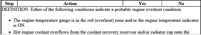
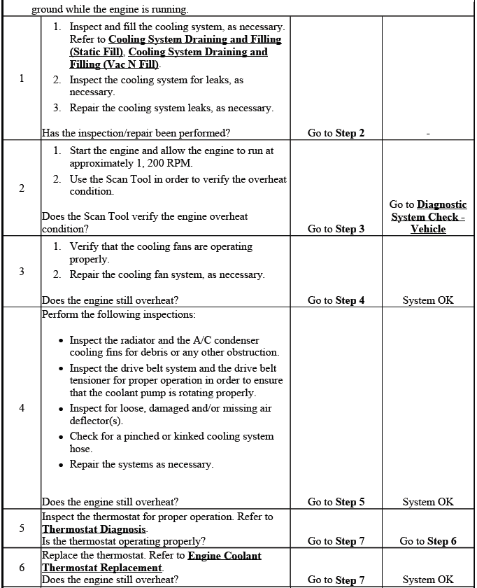
ENGINE OVERHEATING
Engine Overheating
Engine overheating should be approached as a complete cooling system concern, not only as a fan problem. Confirm the coolant level, coolant mixture, radiator airflow, thermostat operation, pressure cap condition, hose integrity, and any signs of external or internal coolant loss. When diagnosing an overheating Buick Enclave, note whether the condition occurs at idle, during highway driving, with the air conditioning ON, while towing or carrying load, or immediately after a cold start. These details help separate airflow faults from coolant circulation faults.
LOSS OF COOLANT
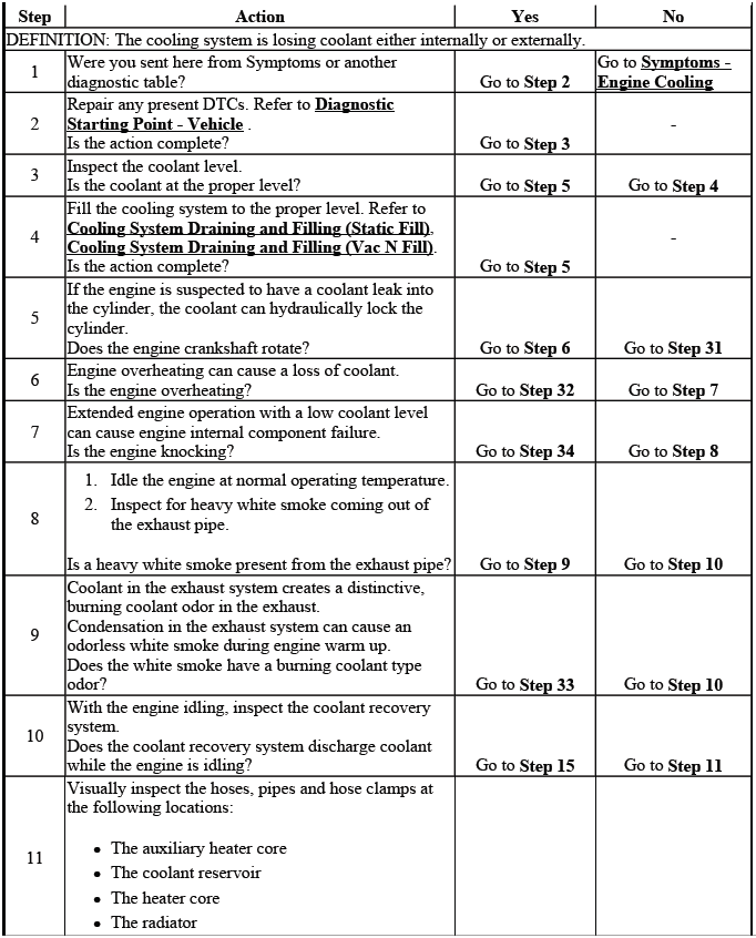
Loss of Coolant
A loss of coolant may be visible or hidden. Visible loss may appear as wet areas around hoses, the radiator, the water pump, the surge tank, the heater core connections, or the engine block. Hidden coolant loss may show up as repeated low coolant level, white exhaust smoke, coolant odor from the vents, contaminated engine oil, or pressure loss during a cooling system pressure test. On the Buick Enclave, a small leak can become more noticeable only after the engine reaches operating temperature and the system is under pressure.
THERMOSTAT DIAGNOSIS
Tools Required
- J 24731 188 Tempilstick
- J 24731 206 Tempilstick
The coolant thermostat can be tested using a temperature, or tempil, stick. The temperature stick is a pencil-like device containing a wax material with chemicals that melt at a specific temperature. Temperature sticks can be used to determine a thermostat's operating range by rubbing 87ºC (188ºF) and 97ºC (206ºF) sticks on the outlet coolant pipe. This method provides a practical check of the temperature range without relying only on scan tool data or an instrument panel gauge reading.
Before testing, the coolant level must be correct and the cooling system should be free of air pockets. Air trapped around the thermostat housing or outlet pipe can delay heat transfer and make the test results misleading. Allow the engine to warm gradually while monitoring the outlet area, and keep hands, clothing, and tools clear of the drive belt, fans, and hot surfaces.
1. Use a tempilstick in order to find the opening and the closing temperatures of the thermostat. Apply the stick to the outlet coolant pipe and watch for the point at which the material begins to melt. The melting point gives a clear indication that the pipe surface has reached the marked temperature.
- J 24731 188 Tempilstick melts at 87ºC (188ºF). The thermostat should begin to open at 90ºC (194ºF). If the outlet pipe remains cool well beyond this point, the thermostat may be stuck closed or coolant circulation may be restricted.
- J 24731 206 tempilstick melts at 97ºC (206ºF). The thermostat should be fully open at 107ºC (225ºF). If the thermostat does not reach full opening in the expected range, the engine may run hotter than intended under load or at low vehicle speed.
2. Replace the thermostat if it does not operate properly between this temperature range. A thermostat that opens too late, opens only partially, sticks closed, or fails to close after cooling can affect warm-up time, heater output, fuel economy, and overall engine temperature stability.
COOLANT HEATER INOPERATIVE
Diagnostic Instructions
- Perform the Diagnostic System Check - Vehicle prior to using this diagnostic procedure.
- Review Strategy Based Diagnosis for an overview of the diagnostic approach.
- Diagnostic Procedure Instructions provides an overview of each diagnostic category.
Circuit/System Description
The coolant heater operates using 110 V AC external power and is designed to warm the coolant in the engine block area for improved starting in very cold weather. The coolant heater also helps reduce fuel consumption when a cold engine is warming up because the engine reaches a more stable operating temperature sooner. The unit is equipped with a detachable AC power cord. There is an internal thermal switch in the coolant heater cord that prevents operation above -18ºC (0ºF). A weather shield on the cord is provided to protect the plug when not in use.
When diagnosing an inoperative coolant heater, inspect the cord, plug, weather shield, connector fit, and the condition of the external power source. A damaged cord, poor outlet connection, tripped breaker, or thermal switch condition can prevent heater operation even when the heater element itself is not damaged. For cold-climate Buick Enclave operation, the cord should be routed away from moving parts, sharp edges, and hot exhaust components, and the plug should be kept clean and dry whenever it is stored.
Reference Information
Electrical Information Reference
Use the following electrical service information when checking the coolant heater circuit, the heater cord, related connectors, and any wiring that may affect operation. A coolant heater concern on the Buick Enclave should be diagnosed as a complete circuit issue, not only as a failed heater element. Poor terminal tension, moisture inside a connector, damaged insulation, or an intermittent open in the cord can create the same customer complaint as a defective heater.
- Circuit Testing
- Connector Repairs
- Testing for Intermittent Conditions and Poor Connections
- Wiring Repairs
Circuit/System Testing
NOTE: The coolant heater cord will read Open due to an internal thermal switch if the ambient temperature is above -18ºC (0ºF). This is a normal operating characteristic of the cord and should not be mistaken for a failed component unless the temperature condition and the rest of the circuit checks confirm a fault.
1. Ignition OFF, disconnect the coolant heater cord from the E19 Coolant Heater. Make sure the external power source is not connected before separating the cord from the heater. Inspect the connector ends for corrosion, water entry, loose terminals, cracked insulation, or signs of overheating. In cold-weather service, the cord is exposed to moisture, road splash, and repeated handling, so a visual inspection is an important part of the diagnosis.
2. Test for 30-40 ohms between the terminals of the E19 Coolant Heater. This resistance range confirms the internal heater element is electrically intact and within the expected operating value. Use clean meter leads and make firm contact with the terminals to avoid a false high reading.
If not within 30-40 ohms
Replace the E19 Coolant Heater. A reading outside this range may indicate an open element, excessive resistance, or an internal short that prevents the coolant heater from warming the engine block area correctly.
If within 30-40 ohms
3. Test for infinite resistance between each terminal of the E19 Coolant Heater and ground. This step checks for unwanted continuity between the heater element and the heater body or ground path. The heater must remain electrically isolated from ground to operate safely and correctly.
If less than infinite resistance
Replace the E19 Coolant Heater. Any measurable resistance to ground indicates an internal fault that may create an unsafe condition or prevent reliable coolant heater operation.
If infinite resistance
4. Test or replace the coolant heater cord. When the heater element tests correctly, the cord becomes the next likely area to inspect. Remember that the cord may read open when the ambient temperature is above the internal thermal switch threshold. If the Buick Enclave is being tested in a warm shop, allow for this temperature-controlled behavior before condemning the cord. Check the plug blades, cord routing, weather shield, and connector fit, and replace the cord if physical damage or confirmed electrical failure is found.
Repair Instructions
Perform the Diagnostic Repair Verification after completing the diagnostic repair. After the repair, confirm that the system operates under the correct temperature conditions and that the cord is routed away from hot exhaust parts, sharp edges, moving components, and areas where road debris can strike it.
- Coolant Heater Replacement
- Coolant Heater Cord Replacement
ENGINE FAILS TO REACH NORMAL OPERATING TEMPERATURE
Engine Fails To Reach Normal Operating Temperature
If the engine does not reach normal operating temperature, do not assume the concern is only related to the thermostat. A cooling system that warms too slowly can be affected by a thermostat stuck open, incorrect coolant level, trapped air, a faulty engine coolant temperature sensor, an inaccurate gauge reading, or operating conditions that keep the engine lightly loaded for long periods. On the Buick Enclave, this condition may also reduce heater performance, increase fuel consumption, and cause the powertrain control system to stay in warm-up strategy longer than expected.
Begin by confirming the actual coolant temperature with a reliable scan tool or temperature-measuring method. Compare the reading to the instrument panel indication and check whether the upper radiator hose warms too early after a cold start. If coolant begins circulating through the radiator before the engine reaches the expected temperature range, the thermostat may be opening too soon or may be stuck partially open.
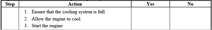
PRESSURE CAP TESTING
Special Tools
- J 24460-01 Cooling System Pressure Tester
- J 42401 Radiator Cap/Surge Tank Test Adapter
Pressure Cap Testing
The pressure cap is a small part of the cooling system, but it has a major effect on boiling point, coolant retention, and pressure stability. A weak cap may allow coolant to escape into the overflow path too early, while a cap that does not release correctly can place excessive pressure on hoses, the radiator, the surge tank, or other cooling system components.
1. Remove the pressure cap.
CAUTION: To avoid being burned, do not remove the radiator cap or surge tank cap while the engine is hot. The cooling system will release scalding fluid and steam under pressure if radiator cap or surge tank cap is removed while the engine and radiator are still hot.
Allow the engine to cool completely before removing the cap. Place a suitable cloth over the cap and turn it slowly to the first stop to release any remaining pressure before removing it fully. Never place your face, hands, or body directly over the cap opening during removal.
2. Wash the pressure cap sealing surface with water. Clean sealing surfaces are necessary for an accurate test. Dirt, dried coolant, or damaged sealing areas can cause pressure loss during testing and may lead to an incorrect diagnosis.
3. Use the J 24460-01 cooling system pressure tester (1) with J 42401 radiator cap/surge tank test adapter (2) in order to test the pressure cap. Make sure the cap is seated squarely on the adapter before applying pressure. An improperly seated cap can leak at the test adapter and appear to fail even when the cap is still serviceable.
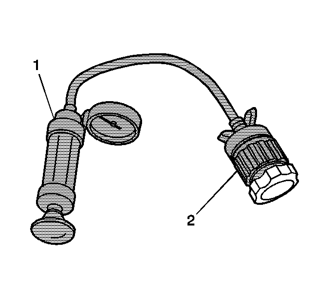
Fig. 2: Identifying Pressure Cap Testing Tool J 42401
IMPORTANT: Lubricate J-42401 and pressure cap o-rings with coolant and press cap to seat o-ring on J-42401 before turning to engage threads. Proper lubrication helps prevent the o-rings from rolling, pinching, or giving a false leak indication during the test.
4. Test the pressure cap for the following conditions. Increase pressure gradually and watch the gauge carefully. The cap should release pressure only when the tester exceeds the specified cap rating, and it should also hold the rated pressure long enough to confirm that the sealing surfaces are working correctly.
- Pressure release when the J 24460-01 cooling system pressure tester exceeds the pressure rating of the pressure cap.
- Maintain the rated pressure for at least 10 seconds.
Note the rate of pressure loss. A slow pressure drop may indicate a cap seal that is worn, contaminated, or not seating evenly against the adapter.
5. Replace the pressure cap under the following conditions:
- The pressure cap does not release pressure which exceeds the rated pressure of the cap.
- The pressure cap does not hold the rated pressure.
A pressure cap that fails either part of the test should not be reused. On a Buick Enclave cooling system, an incorrect or weak cap can contribute to coolant loss, overheating, low heater output, or repeated low-coolant complaints after normal driving.
COOLING SYSTEM LEAK TESTING
Special Tools
- J-24460-01 Cooling System Pressure Tester
Cooling system leak testing is used to locate external leaks and confirm that the system can hold pressure. This test is especially useful when coolant loss is small, intermittent, or only visible after the engine has been driven and the system has reached pressure.
1. Remove the pressure cap.
WARNING: Under pressure, the temperature of the solution in the radiator can be considerably higher, without boiling. Removing the radiator cap while the engine is hot (pressure is high), will cause the solution to boil instantaneously, with explosive force. The solution will spew out over the engine, fenders and the person removing the cap.
Serious bodily injury may result. Flammable antifreeze, such as alcohol, is not recommended for use at any time. Flammable antifreeze could cause a serious fire.
WARNING: In order to help avoid being burned, do not remove the radiator cap while the engine and the radiator are hot. Scalding fluid and steam can be blown out under pressure if the cap is removed too soon.
Before connecting the tester, inspect the coolant level and look for obvious evidence of leakage around the radiator, surge tank, hoses, clamps, water pump area, heater hose connections, thermostat housing, and engine block. Dried coolant residue, white or colored staining, coolant odor, or damp areas can help identify the leak path before pressure is applied.
2. Test the operation of the pressure cap. Refer to Pressure Cap Testing. A faulty cap can cause the system to lose pressure and coolant without an obvious component leak, so the cap should be verified before the rest of the system is judged.
3. Use the J-24460-01 tester in order to apply pressure to the cooling system. Apply pressure slowly and stop at the rated pressure of the cap. Do not use excessive pressure in an attempt to force a leak to appear, because this can damage components that were not originally faulty.
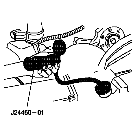
Fig. 3: Pressure Testing Cooling System Using J 24460-01
Do not exceed the pressure cap rating. Exceeding the rated pressure can stress hoses, seals, the radiator, the heater core, or the surge tank and may create a leak that was not present during normal vehicle operation.
4. The cooling system should hold the rated pressure for at least 2 minutes. During this time, observe the tester gauge and inspect the vehicle from above and below. Some leaks may appear only as a small bead of coolant, while others may show as a slow pressure loss without immediate dripping.
Observe the gauge for any pressure loss. If the gauge drops, recheck the tester connection first, then inspect the cooling system carefully. On the Buick Enclave, also pay attention to areas where coolant can collect and hide, such as under shields, around hose junctions, or near the lower engine area.
5. Repair any leaks as required. After repairs are completed, refill the system with the correct coolant mixture, bleed air as required, bring the engine to operating temperature, and repeat the pressure check if needed. Final verification should confirm that the cooling system holds pressure, the engine warms normally, and no coolant odor or visible leakage remains.
