Buick Enclave: Description and Operation
COOLING FAN DESCRIPTION AND OPERATION
Fig. 49: Cooling Fan Description and Operation
The engine cooling fan system uses 2 electric cooling fans and 3 fan relays to control airflow through the radiator and A/C condenser. These relays are arranged in a series/parallel configuration, allowing the engine control module (ECM) to operate both fans together at either low speed or high speed. Battery positive voltage is supplied from the underhood fuse block to the cooling fan relays, and the relays then provide voltage to the cooling fan motors as commanded by the ECM.
In normal operation, the Buick Enclave cooling fan strategy changes fan speed according to engine temperature, air conditioning demand, vehicle speed, and other operating conditions. Low speed is used when moderate airflow is enough to keep the cooling system stable. High speed is used when the engine or A/C system requires stronger airflow, such as during hot weather, extended idling, heavy traffic, or higher thermal load.
During low speed operation, the ECM supplies the ground path for the low speed fan 1 relay through the fan 1 relay control circuit. This energizes the fan 1 relay coil, closes the relay contacts and supplies battery positive voltage from the Fan 1 fuse through the cooling fan motor supply voltage circuit to the left engine cooling fan. This relay action begins the low-speed fan circuit and allows both fan motors to operate together with reduced speed and current demand.
The ground path for the left cooling fan is through the S/P fan 2 relay and the right engine cooling fan. The result is a series circuit with both fans running at low speed. In this series arrangement, current flows through both fan motors in a controlled path, which lowers fan speed while still pulling air across the heat exchangers.
During high speed operation the ECM continues to supply battery positive voltage for the right cooling fan by grounding the coil of the fan 1 relay. The ECM also grounds the high speed fan 3 relay and the S/P fan 2 relay through the fan 3 relay control circuit. This energizes the S/P fan 2 relay coil, closes the relay contacts and provides a direct ground path for the left engine cooling fan. At the same time the fan 3 relay coil is energized closing the relay contacts and providing battery positive voltage from the Fan 2 fuse on the cooling fan motor supply voltage circuit to the right cooling fan. During high speed fan operation, both engine cooling fans have their own ground path. The result is a parallel circuit with both fans running at high speed.
Because the system depends on relay switching and clean electrical paths, poor terminals, weak grounds, relay contact wear, fuse issues, or high resistance in the fan motor circuits can change how the fans operate. A fan that runs at one speed but not the other does not always mean the fan motor itself has failed. The relay configuration and control circuits should be checked as part of a complete diagnosis.
COOLING SYSTEM DESCRIPTION AND OPERATION
The cooling system's function is to maintain an efficient engine operating temperature during all engine speeds and operating conditions. The cooling system is designed to remove approximately one-third of the heat produced by the burning of the air-fuel mixture. When the engine is cold, the coolant does not flow to the radiator until the thermostat opens. This allows the engine to warm quickly.
On the Buick Enclave, stable cooling system operation is important not only for preventing overheating, but also for heater performance, fuel efficiency, emission control, and engine durability. The system must warm the engine quickly after a cold start, then remove heat efficiently once the engine reaches its normal operating range.
Cooling Cycle
Coolant is drawn from the radiator outlet to the thermostat. The flow of coolant will be stopped at the thermostat until the engine is warmed; while the thermostat is closed the water pump circulates coolant through the engine block and heater core. Coolant is returned to the water pump through the engine bypass and the heater core outlet hose. This provides the passenger compartment with heat and defrost. This closed-thermostat circulation also helps reduce warm-up time by keeping coolant movement mostly within the engine and heater circuits.
After the thermostat opens, the coolant is pumped through the water pump outlet and into the engine block and heater core. In the engine block, the coolant circulates through the water jackets surrounding the cylinders where it absorbs heat. As the coolant moves through these passages, it removes heat from areas exposed to combustion and friction.
The coolant is then forced through the cylinder head gasket openings and into the cylinder heads. In the cylinder heads, the coolant flows through the water jackets surrounding the combustion chambers and valve seats, where it absorbs additional heat. These areas experience high thermal load, so steady coolant flow is necessary to prevent hot spots and maintain proper engine operation.
From the cylinder heads, the coolant is then forced into the radiator where it is cooled and the coolant cycle is completed. The radiator transfers heat from the coolant to the outside air, and the cooled fluid returns to the engine to repeat the cycle.
Operation of the cooling system requires proper functioning of all cooling system components. A problem in one area, such as low coolant level, a weak pressure cap, restricted airflow, a stuck thermostat, or a damaged hose, can affect the entire system. The cooling system consists of the following components:
Coolant
The engine coolant is a solution made up of a 50/50 mixture of DEX-COOL and suitable drinking water. The coolant solution carries excess heat away from the engine to the radiator, where the heat is dissipated to the atmosphere. The correct mixture also provides freeze protection, raises the boiling point, and protects internal cooling system surfaces from corrosion. Using the wrong coolant, contaminated water, or an incorrect mixture can reduce heat transfer and may lead to deposits, corrosion, or overheating concerns.
Radiator
The radiator is a heat exchanger consisting of a core and 2 tanks. The aluminum core is a tube and fin crossflow design that extends from the inlet tank to the outlet tank. Fins are placed around the outside of the tubes to improve heat transfer to the atmosphere.
The inlet and outlet tanks are a molded, high temperature, nylon reinforced plastic material. A high temperature rubber gasket seals the tank flange edge to the aluminum core. The tanks are clamped to the core with clinch tabs. The tabs are part of the aluminum header at each end of the core. These joints must remain sealed under heat, vibration, and pressure changes. Coolant staining near a tank seam may indicate a small leak that becomes more visible after the system is hot.
Heat is removed from the coolant as the coolant passes through the radiator. The fins on the core transfer heat from the coolant passing through the tubes. Air passing between the fins absorbs the heat and cools the coolant. Clean fins and correct airflow are critical; dirt, leaves, insects, bent fins, missing seals, or a poorly installed fan shroud can reduce cooling efficiency even when the radiator itself is not leaking.
Pressure Cap
The pressure cap seals and pressurizes the cooling system. The cap contains a blow off or pressure valve and a vacuum or an atmospheric valve:
- The pressure valve is held against the seat by a spring that protects the radiator by relieving pressure that exceeds 15 psi.
- The vacuum valve is held against the seat by a spring that permits opening of the valve to relieve vacuum created when the cooling system cools. The vacuum, if not relieved, might cause the radiator to collapse.
The pressure cap allows the cooling system pressure to build up when the temperature increases. As the pressure builds, the boiling point of the coolant increases. Therefore, the engine coolant can be safely run at a temperature much higher than the boiling point of the coolant at atmospheric pressure. The hotter the coolant becomes, the faster the heat transfers from the radiator into the cooler air.
The pressure in the cooling system can get too high. When the pressure exceeds the strength of the spring, the pressure valve rises, venting the excess pressure. This controlled release protects cooling system components from pressure that is beyond the cap rating.
As the engine cools, the temperature of the coolant drops and a vacuum is created in the cooling system. This vacuum causes the vacuum valve to open. This equalizes the pressure in the cooling system with the atmospheric pressure, preventing the radiator from collapsing.
A weak, contaminated, incorrect, or damaged pressure cap can cause coolant loss, poor recovery from the reservoir, overheating, or repeated low-coolant complaints. For this reason, cap condition should be checked whenever pressure loss or coolant recovery issues are present.
Coolant Recovery System
The coolant recovery system consists of a plastic coolant recovery reservoir and overflow tube. The recovery reservoir is also called a recovery tank or expansion tank. This tank is partially filled with coolant and is connected to the radiator fill neck with the overflow tube. Coolant can flow back and forth between the radiator and the reservoir.
In effect, a cooling system with a coolant recovery reservoir is a closed system. When the pressure within the cooling system gets too high, the pressure valve in the pressure cap will open. This allows the coolant, which has expanded due to heat, to flow through the overflow tube and into the recovery reservoir. As the engine cools down, the temperature of the coolant drops and a vacuum is created in the cooling system. This vacuum opens the vacuum valve in the pressure cap, allowing some of the coolant in the reservoir to be siphoned back into the radiator. Under normal operating conditions, no coolant is lost. Although the coolant level in the recovery reservoir goes up and down, the radiator and cooling system are kept full. An advantage to using a coolant recovery reservoir is the elimination of almost all air bubbles from the cooling system. Coolant without bubbles absorbs heat much better than coolant with bubbles.
For the Buick Enclave cooling system, the reservoir level should be checked when the engine is cool and compared with the proper level markings. A reservoir that is overfilled, underfilled, cracked, or connected to a damaged overflow hose can cause misleading coolant level changes and may allow air to enter the system.
Air Baffles and Seals
The cooling system uses deflectors, air baffles and air seals to increase cooling system capability. Deflectors are installed under the vehicle to redirect airflow beneath the vehicle and through the radiator to increase engine cooling. Air baffles are also used to direct airflow through the radiator and increase cooling capability. Air seals prevent air from bypassing the radiator and A/C condenser and prevent recirculation of hot air for better hot weather cooling and A/C condenser performance.
These airflow parts are often overlooked because they do not carry coolant, but they are essential to the way the cooling package is designed. Missing or incorrectly installed baffles may allow air to move around the radiator instead of through it, which can cause high temperature complaints during slow driving, idling, or air conditioning use.
Transmission Oil Cooler
The transmission oil cooler is a heat exchanger that is located inside one of the radiator end tanks. The transmission fluid temperature is regulated by the temperature of the engine coolant in the radiator. The oil pump pumps the fluid through the transmission oil cooler feed line to the oil cooler. The fluid flows through the cooler where the engine coolant absorbs heat from the fluid. The fluid is then pumped through the oil cooler return line back to the transmission.
If the radiator is replaced or if cooler lines are disconnected, the transmission oil cooler connections should be inspected carefully for correct seating and leakage. A poor connection can lead to fluid loss, while a restricted cooler passage can affect transmission temperature control.
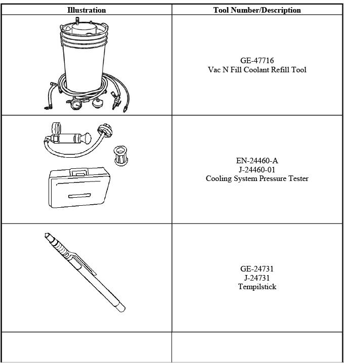
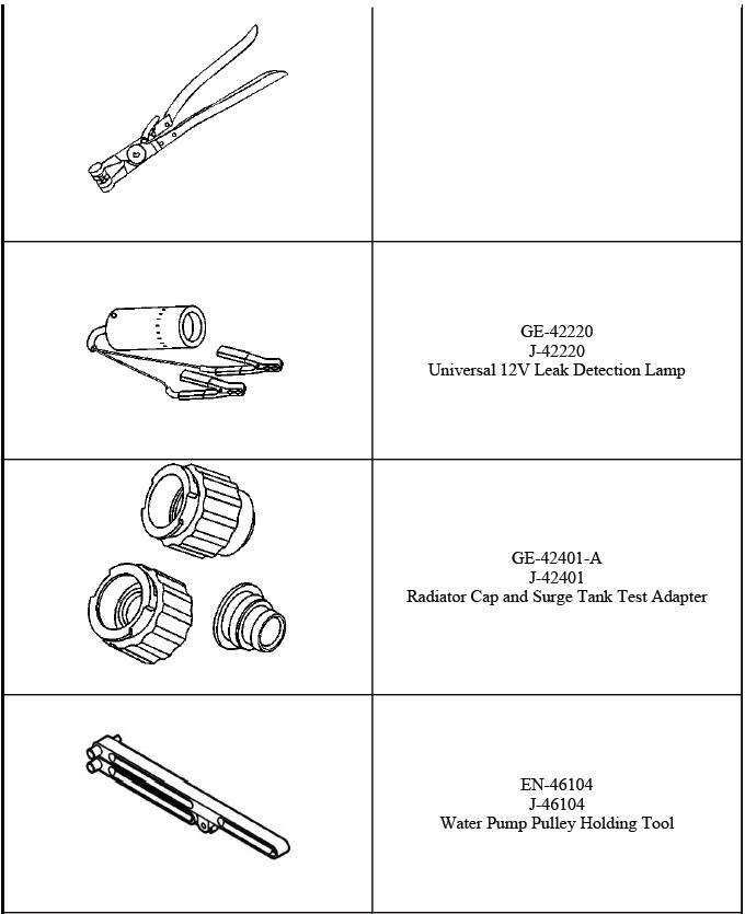
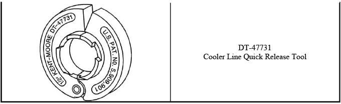
SPECIAL TOOLS AND EQUIPMENT
SPECIAL TOOLS
Special tools are used to service the cooling system accurately and safely. Correct tools help prevent damage to fittings, caps, seals, hoses, and pressure-test connections. When working on the Buick Enclave, always match the tool to the procedure and inspect tool seals or adapters before use.
Firing Order & Cylinder Identification
FIRING ORDER & CYLINDER IDENTIFICATION
NOTE: This information is intended as a quick reference for firing order and cylinder identification only. The information provided covers many vehicles and may include some information that does not apply to the vehicle you have currently selected.
This section provides general cylinder identification and firing order reference illustrations. Because the reference covers several engine families, always confirm the exact engine configuration before applying a diagram to a specific repair. For Buick Enclave service work, use the diagram that matches the installed V6 engine and avoid using unrelated engine layouts from the general reference group.
3 CYLINDER ENGINE
4 CYLINDER ENGINE
5 CYLINDER ENGINE
IN-LINE 6 ENGINE
V6 ENGINE
The V6 engine references are the most relevant portion of this section for Buick Enclave engine identification. Cylinder numbering and firing order information is useful during ignition diagnosis, injector testing, compression checks, misfire diagnosis, and any repair where the correct bank or cylinder must be identified before parts are removed.
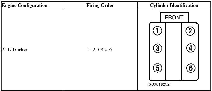
2.5L V6 Engine - Tracker
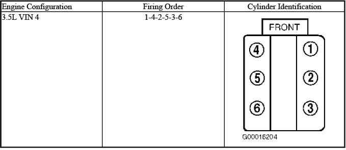
3.5L VIN 4 V6 Engine
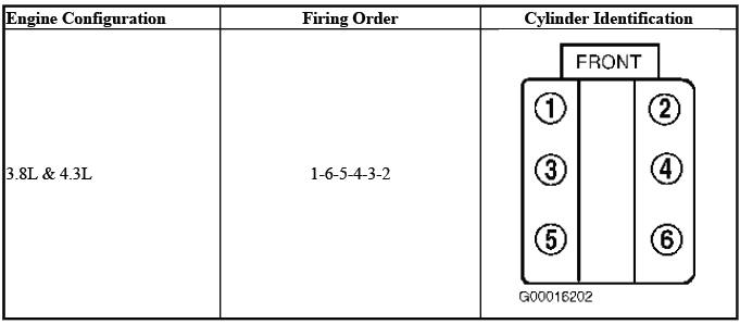
3.8L & 4.3L V6 Engines
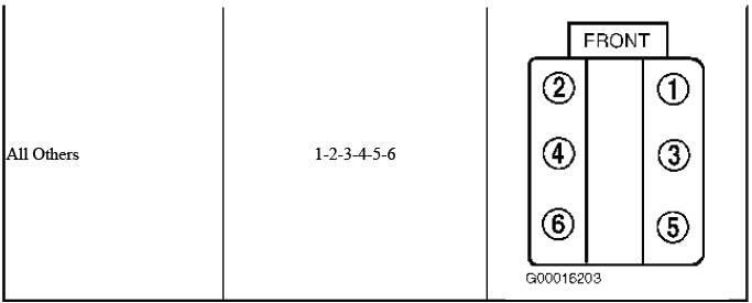
All Other V6 Engines
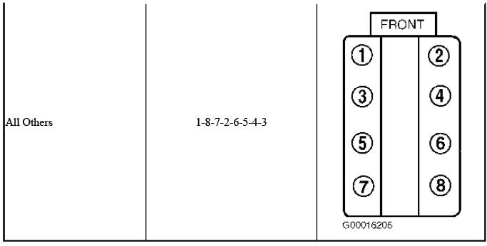
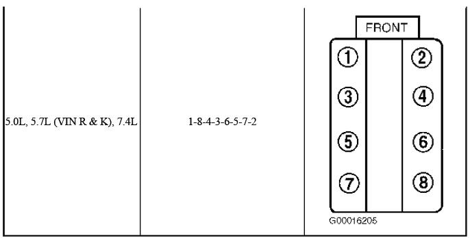
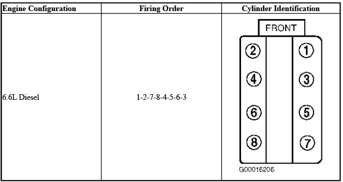
8 CYLINDER ENGINE
The following V8 illustrations are included as part of the broader reference information. They should be used only when the engine type matches the vehicle being serviced. They are not a substitute for confirming the correct engine family, displacement, and service manual section before performing ignition or cylinder-specific diagnosis.
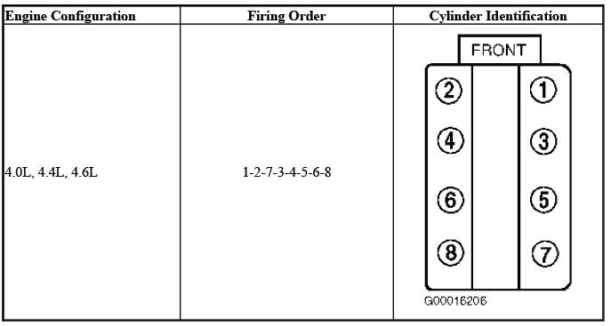
4.0L, 4.4L & 4.6L V8 Engines
5.0L, 5.7L (VIN R & VIN K) & 7.4L V8 Engines
6.6L Diesel V8 Engine
All Other V8 Engines