Buick Enclave: Repair Instructions - On Vehicle
TRANSFER CASE FLUID REPLACEMENT
Removal Procedure
1. Raise and support the vehicle. Refer to Lifting and Jacking the Vehicle. The vehicle must be stable and level before the transfer case is drained, because an uneven position can affect the fluid level reading during refill and may create a safety risk while working underneath.
2. Remove the drain plug. Place a suitable drain pan under the transfer case before loosening the plug, then allow the lubricant to drain completely. Watch the fluid as it comes out; dark color, burnt odor, water contamination, or metallic particles can indicate internal wear or overheating that should be investigated before the vehicle is returned to service.
Fig. 2: Identifying Drain Plug
3. Remove the fill plug. Removing the fill plug after opening the drain plug helps the case vent while draining and also confirms that the fill plug can be removed before the unit is emptied. If the fill plug is seized or damaged, correct that condition before completing the service.
Fig. 3: Identifying Fill Plug
Installation Procedure
1. Clean the drain plug. Remove old fluid residue, metal paste, dirt, and any sealant from the plug and sealing surface. If the plug threads are damaged or the sealing face is distorted, replace the plug rather than reinstalling a part that may leak.
Fig. 4: Identifying Drain Plug
2. Install the drain plug and tighten to 39 (29 lb ft). Tighten the plug evenly and do not over-torque it. Excessive force can damage the threads or sealing surface, while insufficient tightening may allow fluid seepage after the transfer case warms up.
CAUTION: Refer to Component Fastener Tightening Caution.
3. Fill the transfer case with lubricant to the bottom of the fill plug or 1 Liter (34 oz). Refer to Adhesives, Fluids, Lubricants and Sealers for lubricant recommendation. Use only the approved fluid, because the transfer case depends on the correct lubricant for bearing protection, gear contact, temperature control, and seal compatibility.
On a Buick Enclave, the final fluid level should be checked by the fill opening method, not only by the measured amount poured into the case. A small amount of old fluid may remain inside, or the case may not have drained fully depending on vehicle angle and temperature.
Fig. 5: Identifying Fill Plug
4. Clean the fill plug. Make sure the threads and sealing area are free of grit, metal particles, and old fluid residue. A clean plug helps prevent a slow leak and reduces the chance of contamination entering the case.
5. Install the fill plug and tighten to 39 (29 lb ft). After tightening, wipe the area dry so any new leakage can be identified during the final inspection.
6. Lower the vehicle. After lowering, road test if required, then recheck the transfer case area for seepage around the drain plug, fill plug, and nearby sealing surfaces.
FILL PLUG REPLACEMENT
Removal Procedure
1. Remove the fill plug. Clean the surrounding area before removal so dirt does not fall into the transfer case. If the plug is tight, use the correct tool fully seated in the plug to avoid rounding the drive area.
Fig. 6: Identifying Fill Plug
Installation Procedure
1. Install the fill plug and tighten to 39 (29 lb ft). Confirm that the plug seats squarely and that the sealing surface is clean. If the plug was replaced because of damage, inspect the case threads before installation to make sure the new plug will seal correctly.
Fig. 7: Identifying Fill Plug
CAUTION: Refer to Component Fastener Tightening Caution.
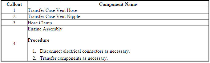
TRANSFER CASE VENT HOSE REPLACEMENT
The transfer case vent hose allows pressure inside the housing to equalize as the lubricant heats, cools, and moves during driving. A blocked, kinked, disconnected, or incorrectly routed vent hose can contribute to fluid leaks by allowing pressure to build inside the case. Before replacing seals for a repeat leak, the vent system should be checked carefully.
When replacing the vent hose, route it in the same path as the original and keep it away from exhaust heat, sharp edges, moving driveline parts, and areas where road debris can strike it. The hose should not be pinched under brackets or stretched tight at either end. For Buick Enclave transfer case service, correct vent routing is a small detail that can prevent unnecessary repeat leak repairs.
Fig. 8: Transfer Case Vent Hose
Transfer Case Vent Hose Replacement
After the new vent hose is installed, confirm that it is fully seated and that the open end is positioned where water, mud, or road splash cannot easily enter. A restricted vent can force lubricant past otherwise good seals, while an open or poorly positioned hose can allow contamination into the transfer case.
REAR OUTPUT SHAFT SEAL REPLACEMENT
Removal Procedure
1. Raise and support the vehicle. Refer to Lifting and Jacking the Vehicle. Make sure the vehicle is secure and that the driveline can be accessed safely before beginning the repair.
2. Drain the transfer case fluid. Refer to Transfer Case Fluid Replacement. Draining the fluid before removing the rear output parts helps prevent spills and allows the technician to inspect the lubricant for signs of internal wear.
3. Remove the rear propeller shaft. Refer to Propeller Shaft Replacement. Mark the relationship of the shaft to the flange if required by the service procedure, and support the shaft properly so the joints are not damaged during removal.
4. Remove the rear output shaft housing. Refer to Rear Output Shaft Housing Removal in Transfer Case Disassemble. Keep the housing straight during removal and avoid prying against machined sealing surfaces.
5. Remove the transfer case rear output shaft flange and seal. Refer to Rear Output Shaft Housing Disassembly in Transfer Case Disassemble. Inspect the flange sealing surface after removal. A groove, rust, burr, or worn contact track can damage the new seal or cause a repeat leak even when the seal itself is installed correctly.
Installation Procedure
1. Install the transfer case rear output shaft seal. Refer to Rear Output Shaft Housing Assembly and Output Flange Installation in Transfer Case Assemble. Use the correct seal installer so the seal enters the bore squarely and reaches the proper depth without distortion.
2. Install the rear output shaft housing. Refer to Rear Output Shaft Housing Installation in Transfer Case Assemble. Clean mating surfaces and use the specified sealing method to prevent fluid seepage around the housing.
3. Install the rear propeller shaft. Refer to Propeller Shaft Replacement. Tighten the fasteners evenly and make sure the shaft is aligned and fully seated.
4. Fill the transfer case with fluid. Refer to Transfer Case Fluid Replacement. Confirm the level at the fill opening and use only the recommended lubricant.
5. Lower the vehicle. After the repair, check for leaks during and after a road test, especially around the rear output seal and housing joint.
REAR OUTPUT SHAFT FLANGE REPLACEMENT
Removal Procedure
1. Raise and support the vehicle. Refer to Lifting and Jacking the Vehicle.
2. Drain the transfer case fluid. Refer to Transfer Case Fluid Replacement. This keeps the work area cleaner and gives an opportunity to check the fluid condition.
3. Remove the rear propeller shaft. Refer to Propeller Shaft Replacement. Avoid letting the shaft hang by the joint or bind against nearby components.
4. Remove the rear output shaft housing. Refer to Rear Output Shaft Housing Removal in Transfer Case Disassemble. Handle the housing carefully so the sealing surfaces are not scratched.
5. Remove the transfer case rear output shaft flange. Refer to Rear Output Shaft Housing Disassembly in Transfer Case Disassemble. Look over the splines, sealing surface, and contact area for damage. If the flange is worn where the seal rides, replacing the seal alone will not correct the leak.
Installation Procedure
1. Install the transfer case rear output shaft flange and slinger. Refer to Rear Output Shaft Housing Assembly and Output Flange Installation in Transfer Case Assemble. The slinger must be positioned correctly because it helps manage oil movement near the seal area.
2. Install the rear output shaft housing. Refer to Rear Output Shaft Housing Installation in Transfer Case Assemble.
3. Install the rear propeller shaft. Refer to Propeller Shaft Replacement. Confirm that the shaft seats correctly and that all fasteners are tightened to the required value.
4. Fill the transfer case with fluid. Refer to Transfer Case Fluid Replacement. Recheck the fill and drain plug areas after filling.
5. Lower the vehicle. Verify that no abnormal vibration, noise, or leakage is present after the repair.
REAR OUTPUT FLANGE OIL SLINGER REPLACEMENT
Removal Procedure
1. Raise and support the vehicle. Refer to Lifting and Jacking the Vehicle. Keep the vehicle level and stable so the transfer case can be drained and serviced safely.
2. Drain the transfer case fluid. Refer to Transfer Case Fluid Replacement.
3. Remove the rear propeller shaft. Refer to Propeller Shaft Replacement. Mark related parts if required so the driveline can be returned to its original orientation.
4. Remove the rear output shaft housing. Refer to Rear Output Shaft Housing Removal in Transfer Case Disassemble. The oil slinger works with the rear output flange and seal area, so inspect all related parts together rather than treating the slinger as an isolated component. On a Buick Enclave, wear or incorrect placement in this area can contribute to leakage, fluid movement problems, or repeat service concerns after the transfer case is assembled.
5. Remove the transfer case rear output shaft flange. Refer to Rear Output Shaft Housing Disassembly in Transfer Case Disassemble. Keep the flange straight during removal and avoid marking the sealing surface, because even a small nick or groove can damage the new seal or create a repeat leak after assembly.
6. Remove the transfer case rear output shaft oil slinger from the transfer case rear output shaft flange. Note the installed direction of the slinger before removal. The slinger helps manage lubricant movement near the rear output area, so incorrect positioning can affect sealing performance and may contribute to fluid seepage during operation.
Installation Procedure
1. Install the transfer case rear output shaft flange and slinger. Refer to Rear Output Shaft Housing Assembly and Output Flange Installation in Transfer Case Assemble. Make sure the slinger is seated in the same orientation as the original part and that the flange surface is clean, smooth, and free of burrs before installation.
2. Install the rear output shaft housing. Refer to Rear Output Shaft Housing Installation in Transfer Case Assemble. Clean the mating surfaces carefully and avoid excessive sealant, since extra material can squeeze into the housing and contaminate the lubricant.
3. Install the rear propeller shaft. Refer to Propeller Shaft Replacement. Support the shaft during installation and confirm that the flange connection is properly aligned before tightening the fasteners.
4. Fill the transfer case with fluid. Refer to Transfer Case Fluid Replacement. Use the approved lubricant and confirm the final level at the fill opening rather than relying only on the amount added.
5. Lower the vehicle. After the Buick Enclave is back on the ground, inspect the rear output area for leaks and verify that no abnormal driveline vibration or noise is present during a careful road test.
INTERMEDIATE DRIVE SHAFT REPLACEMENT
Removal Procedure
1. Raise and support the vehicle. Refer to Lifting and Jacking the Vehicle. The vehicle must be secure and level before the transfer case is drained or removed, because the work involves both fluid service and driveline component handling.
2. Drain the transfer case fluid. Refer to Transfer Case Fluid Replacement. Inspect the drained fluid for metal particles, discoloration, burnt odor, or water contamination. These signs may point to internal wear that should be considered before the new or serviced shaft is installed.
3. Remove the transfer case assembly (2). Refer to Transfer Case Assembly Replacement. Support the transfer case correctly during removal so the housing, mounting points, seals, and surrounding components are not damaged.
Fig. 9: Identifying Transfer Case & Bolts
4. Remove the intermediate shaft snap ring and intermediate drive shaft from the transfer case. Refer to Intermediate Drive Shaft Removal in Transfer Case Disassemble. Use care when removing the snap ring, because distortion or loss of tension can prevent secure retention during reassembly.
5. Remove the O-ring, half shaft retainer, intermediate shaft bearing retainer and bearing from the intermediate drive shaft. Refer to Intermediate Drive Shaft Disassembly in Transfer Case Disassemble. Keep the parts in order and check each contact surface for scoring, wear, corrosion, or signs of overheating.
Installation Procedure
1. Install the O-ring, half shaft retainer, intermediate shaft bearing retainer and bearing to the intermediate drive shaft. Refer to Intermediate Drive Shaft Assembly in Transfer Case Assemble. Lightly lubricate sealing surfaces where the service procedure allows it, and make sure the O-ring is not twisted or pinched during assembly.
2. Install the intermediate shaft and snap ring into the transfer case. Refer to Intermediate Drive Shaft Assembly in Transfer Case Assemble. Confirm that the snap ring seats fully in its groove and that the shaft is retained securely before the transfer case is installed back into the vehicle.
NOTE: Special tool DT-48094 must be used to install the intermediate shaft.
3. Install the transfer case assembly (2). Refer to Transfer Case Assembly Replacement. Align the case carefully with the mounting points and avoid using the bolts to force the housing into position. If the case does not seat correctly, stop and check for misalignment or interference.
Fig. 10: Identifying Transfer Case & Bolts
4. Fill the transfer case with fluid. Refer to Transfer Case Fluid Replacement. Correct fluid level is important for bearing and shaft durability, especially after the transfer case has been removed and internal parts have been disturbed.
5. Lower the vehicle. After installation, check for leaks, confirm proper driveline operation, and listen for abnormal noise during a controlled road test.
INTERMEDIATE DRIVE SHAFT BEARING REPLACEMENT
Removal Procedure
1. Raise and support the vehicle. Refer to Lifting and Jacking the Vehicle. Make sure there is enough room to remove the transfer case safely and to support the assembly without putting stress on nearby components.
2. Drain the transfer case fluid. Refer to Transfer Case Fluid Replacement. Fluid inspection is useful during bearing replacement because metal debris or dark lubricant may confirm bearing wear or internal contact.
3. Remove the transfer case assembly (2). Refer to Transfer Case Assembly Replacement. Keep the unit level where possible to reduce fluid spill and prevent damage to sealing surfaces.
Fig. 11: Identifying Transfer Case & Bolts
4. Remove the intermediate shaft snap ring and intermediate drive shaft from the transfer case. Refer to Intermediate Drive Shaft Removal in Transfer Case Disassemble. Do not pry against machined surfaces; use the correct removal method so the housing and shaft are not damaged.
5. Remove the intermediate shaft bearing retainers and bearing from the intermediate drive shaft. Refer to Intermediate Drive Shaft Disassembly in Transfer Case Disassemble. Rotate the bearing by hand after removal if possible. Roughness, looseness, discoloration, or metal flakes around the bearing area are signs that related parts should be checked closely.
Installation Procedure
1. Install the intermediate shaft bearing and retainers to the intermediate drive shaft. Refer to Intermediate Drive Shaft Assembly in Transfer Case Assemble. The bearing must be installed squarely and supported by the correct surface, because pressing on the wrong race can damage a new bearing before the vehicle is even driven.
2. Install the intermediate shaft and snap ring into the transfer case. Refer to Intermediate Drive Shaft Assembly in Transfer Case Assemble. Verify that the bearing, retainers, shaft, and snap ring are fully seated and that the shaft turns smoothly without binding.
NOTE: Special tool DT-48094 must be used to install the intermediate shaft.
3. Install the transfer case assembly (2). Refer to Transfer Case Assembly Replacement. During installation on a Buick Enclave, confirm that the transfer case mates evenly and that wiring, brackets, and nearby driveline parts are not trapped between components.
Fig. 12: Identifying Transfer Case & Bolts
4. Fill the transfer case with fluid. Refer to Transfer Case Fluid Replacement. Use only the specified lubricant and check the level after the vehicle has been positioned correctly.
5. Lower the vehicle. Once the vehicle is lowered, perform a final leak check and listen for bearing-related noise during the first road test after service.
INTERMEDIATE DRIVE SHAFT SEAL REPLACEMENT
Removal Procedure
1. Raise and support the vehicle. Refer to Lifting and Jacking the Vehicle. A stable setup is necessary because the transfer case assembly must be removed before the seal can be serviced properly.
2. Drain the transfer case fluid. Refer to Transfer Case Fluid Replacement. Draining the lubricant reduces spillage and gives the technician a chance to look for contamination that may have affected the seal or shaft surface.
3. Remove the transfer case assembly (2). Refer to Transfer Case Assembly Replacement. Handle the case carefully and protect the sealing areas from scratches, dents, or dirt.
Fig. 13: Identifying Transfer Case & Bolts
4. Remove the intermediate shaft snap ring and intermediate drive shaft from the transfer case. Refer to Intermediate Drive Shaft Removal in Transfer Case Disassemble. Keep the shaft aligned during removal so the seal bore, bearing area, and shaft surface are not damaged.
5. Remove the half shaft retainer and O-ring seal from the intermediate drive shaft. Refer to Intermediate Drive Shaft Disassembly in Transfer Case Disassemble. Inspect the groove, retainer, and shaft surface before installing the new seal. Dirt, corrosion, sharp edges, or a damaged groove can cut the O-ring and cause a repeat leak.
Installation Procedure
1. Install the O-ring seal and half shaft retainer to the intermediate drive shaft. Refer to Intermediate Drive Shaft Assembly in Transfer Case Assemble. Make sure the O-ring sits evenly in its groove and is not rolled, stretched, or pinched by the retainer. A small amount of approved lubricant may help the seal seat cleanly during assembly when allowed by the service procedure.
2. Install the intermediate shaft and snap ring into the transfer case. Refer to Intermediate Drive Shaft Assembly in Transfer Case Assemble. Make sure the shaft is seated straight in the bore and that the snap ring locks fully into its groove. A partially seated snap ring can allow shaft movement, noise, leakage, or internal damage after the vehicle is returned to service.
NOTE: Special tool DT-48094 must be used to install the intermediate shaft.
3. Install the transfer case assembly (2). Refer to Transfer Case Assembly Replacement. Align the transfer case carefully with the transmission and avoid forcing the unit into position with the mounting bolts. If the housing does not seat smoothly, stop and check for interference, seal misalignment, or debris on the mating surface.
Fig. 14: Identifying Transfer Case & Bolts
4. Fill the transfer case with fluid. Refer to Transfer Case Fluid Replacement. Use the specified lubricant and verify the level by the correct fill procedure, since proper fluid level is critical for bearing life, gear lubrication, and seal durability.
5. Lower the vehicle. After lowering, check the serviced area for leaks and confirm that no abnormal driveline noise or vibration is present during a controlled road test.
REAR OUTPUT SHAFT HOUSING O-RING SEAL REPLACEMENT
Removal Procedure
1. Raise and support the vehicle. Refer to Lifting and Jacking the Vehicle. The vehicle should be secure and level before the rear output shaft housing is removed.
2. Drain the transfer case fluid. Refer to Transfer Case Fluid Replacement. Draining the fluid reduces spillage and gives the technician a chance to check the lubricant for metal particles, water contamination, or signs of overheating.
3. Remove the rear propeller shaft. Refer to Propeller Shaft Replacement. Support the shaft during removal so the joints are not damaged, and mark the relationship of the shaft to the flange if the service procedure requires it.
4. Remove the rear output shaft housing. Refer to Rear Output Shaft Housing Removal in Transfer Case Disassemble. Keep the housing square during removal and avoid prying against machined sealing surfaces.
5. Remove the transfer case rear output shaft housing seal O-ring. Inspect the O-ring groove and surrounding sealing face for corrosion, dirt, cuts, or old seal material. A damaged groove or dirty sealing surface can cause a new O-ring to leak even when it is installed correctly.
Installation Procedure
1. Install the transfer case rear output shaft housing seal O-ring. Lightly lubricate the O-ring where the procedure allows it, and make sure it sits flat in the groove without twisting, stretching, or rolling.
2. Install the rear output shaft housing. Refer to Rear Output Shaft Housing Installation in Transfer Case Assemble. Slide the housing into position evenly so the O-ring is not pinched or cut during installation.
3. Install the rear propeller shaft. Refer to Propeller Shaft Replacement. Confirm that the shaft is aligned correctly and that all fasteners are tightened according to the proper service procedure.
4. Fill the transfer case with fluid. Refer to Transfer Case Fluid Replacement. Check the final level at the fill opening and clean any spilled fluid from the housing so new leaks can be identified easily.
5. Lower the vehicle. On a Buick Enclave, recheck the rear output housing area after a short road test because some leaks appear only after the lubricant warms up and the case is under normal operating load.
TRANSFER CASE ASSEMBLY REPLACEMENT
Removal Procedure
1. Raise and support the vehicle. Refer to Lifting and Jacking the Vehicle. Use a safe lifting method and confirm that the vehicle is stable before removing driveline, exhaust, or mounting components.
2. Drain the transfer case fluid. Refer to Transfer Case Fluid Replacement. Inspect the drained fluid for contamination or metal debris that may indicate internal transfer case wear.
3. Drain the transmission fluid. Refer to Transmission Fluid Drain and Fill. This helps prevent fluid loss when the transfer case is separated from the transmission and keeps the work area cleaner.
4. Remove the propeller shaft. Refer to Propeller Shaft Replacement. Keep the shaft supported and avoid stressing the joints during removal.
5. Remove the right wheel drive shaft. Refer to Front Wheel Drive Shaft Replacement. Protect the shaft splines and seals from damage while the shaft is being removed from the assembly.
6. Remove the exhaust flexible pipe. Refer to Exhaust Flexible Pipe Replacement. Allow the exhaust to cool before handling it, and support the system as needed so nearby parts are not strained.
7. Support the transaxle with a jackstand. The support must be positioned securely because removing the transfer case and mount bracket can change how the drivetrain load is carried.
8. Remove the engine rear mount bracket. Refer to Engine Rear Mount Bracket Replacement (Front Wheel Drive) and Engine Rear Mount Bracket Replacement (All Wheel Drive). Keep track of bracket position and fastener locations for accurate reassembly.
9. Remove the transfer case bolts (1). Loosen the bolts evenly and support the transfer case before the final fasteners are removed. Do not let the unit hang from the transmission bore or remaining hardware.
Fig. 15: Identifying Transfer Case & Bolts
10. Remove the transfer case (2). Work the transfer case away from the transmission carefully. If resistance is felt, check again for hidden fasteners, seal drag, alignment pins, or components still attached. Avoid using excessive prying force that could damage the housing or transmission mating surface.
Installation Procedure
1. Lubricate the O-rings (2, 3) with automatic transmission fluid. Lubrication helps the seals slide into position without rolling, tearing, or being cut during transfer case installation.
Fig. 16: Identifying Transfer Case O-Ring Seal, Half Shaft Retainer &
Intermediate Shaft Seals
2. Install the NEW transfer case O-ring seal (3). Do not reuse an old O-ring, even if it appears undamaged. Once compressed, the seal may not recover enough to prevent leakage after reassembly.
3. Carefully insert a clean soft cloth into the transmission torque converter housing differential bore to prevent debris from entering the transmission. The cloth should block loose particles but must be positioned so it can be removed completely before installation continues.
Fig. 17: View Of Torque Converter Housing Differential Bore
NOTE: Oxidation must be removed from the transmission torque converter housing bore before installation of the transfer case. A clean bore will prevent oxidation build up from scuffing or cutting the O-ring seal upon transfer case installation, resulting in a leak.
4. Clean the oxidation from the transmission torque converter housing differential bore surface using steel wool or crocus cloth. Work carefully and remove only oxidation or residue, not base material. The goal is a clean, smooth bore that will not scrape the new O-ring during installation.
5. Carefully remove any debris and the cloth from the transmission torque converter housing differential bore. Use light and inspection tools as needed to confirm that no fibers, metal particles, oxidation dust, or loose debris remain inside the bore.
6. Fabricate 2 guide pins by cutting the heads off of 2 bolts M12x1.75x75. Chamfer and remove burrs from the cut end of the bolt. Smooth guide pins protect the new O-ring and help the transfer case slide into alignment without dropping or twisting against the transmission.
Fig. 18: Identifying Guide Pins
NOTE: Use guide pins to aid in alignment and installation of the transfer case to the transmission. Failure to use guide pins may result in cutting the transfer case O-ring seal during installation of the transfer case causing a fluid leak.
7. Hand thread the guide pins (1) into the transmission upper and lower transfer case mounting bolt holes. Thread them in far enough to support alignment, but do not overtighten them or damage the transmission threads.
8. Thoroughly clean the transmission bore and ribbing of fluid and debris immediately prior to installing the transfer case. This final cleaning step matters because fluid can carry grit into the sealing area and debris on the ribs can fall into the bore while the case is being positioned.
NOTE: Transmission fluid may creep from the transmission bore during installation.
9. Install the transfer case (1) to the transmission. Keep the transfer case level and slide it over the guide pins with steady pressure. On the Buick Enclave, the case should move into place without forcing; if it does not, remove it and check the O-ring, guide pin alignment, and mating surfaces before trying again.
Fig. 19: View Of Transfer Case & Transmission
10. Remove the guide pins (2). Remove them carefully so the transfer case does not shift away from the transmission or disturb the O-ring seal.
11. Install the transfer case to transmission bolts (1) and tighten to 50 N.m (37 lb ft). Tighten the bolts evenly and confirm that the housing remains fully seated against the transmission. After installation, continue with the remaining components, refill the fluids, and inspect for leaks during final verification.
Fig. 20: View Of Transfer Case & Bolts
CAUTION: Refer to Fastener Caution.
12. Install the engine rear mount bracket. Refer to Engine Rear Mount Bracket Replacement (Front Wheel Drive), Engine Rear Mount Bracket Replacement (All Wheel Drive). Position the bracket correctly before tightening the fasteners, and make sure the mount is not under twist or side load. A misaligned mount can transfer vibration into the body and may place unnecessary stress on the transfer case and transaxle assembly.
13. Remove the jackstand from under the transaxle. Do this only after the rear mount bracket and related support components are fully installed and tightened. The drivetrain should settle naturally into position without sudden movement or binding.
14. Install the exhaust flexible pipe. Refer to Exhaust Flexible Pipe Replacement. Check that the flex section is not twisted and that the exhaust system has clearance from the transfer case, brackets, shields, and underbody parts. Improper exhaust alignment can cause noise, vibration, or heat damage near driveline components.
15. Install the right wheel drive shaft. Refer to Front Wheel Drive Shaft Replacement. Protect the shaft seal and splines during installation, and confirm that the shaft seats fully. A half-installed shaft can create fluid leakage, vibration, or drive engagement problems.
16. Install the propeller shaft. Refer to Propeller Shaft Replacement. Align the shaft correctly, support it during installation, and tighten the fasteners evenly. If match marks were made during removal, return the shaft to its original position to reduce the chance of driveline vibration.
17. Fill the transfer case with fluid. Refer to Transfer Case Fluid Replacement. Use only the specified lubricant and verify the final level by the approved fill procedure. Correct fluid level is important for bearing life, gear lubrication, temperature control, and seal durability.
18. Fill the transmission fluid. Refer to Transmission Fluid Drain and Fill. After filling, follow the correct temperature and level-check procedure. Transmission fluid level should not be guessed, because both overfilling and underfilling can affect shift quality and component life.
19. Lower the vehicle. After the vehicle is on the ground, inspect for leaks around the transfer case, transmission mating area, fill plugs, shaft seals, and any lines or components disturbed during service. A short controlled road test should be followed by another visual inspection.
INPUT SHAFT SEAL REPLACEMENT
Removal Procedure
1. Raise and support the vehicle. Refer to Lifting and Jacking the Vehicle. Make sure the vehicle is stable and level before working underneath. This repair requires access to driveline, exhaust, mounting, and transfer case components, so safe support is essential.
2. Drain the transfer case fluid. Refer to Transfer Case Fluid Replacement. While the lubricant drains, check for metal particles, burnt odor, water contamination, or heavy discoloration. These clues may indicate internal wear that should be considered before the unit is reinstalled.
3. Remove the propeller shaft. Refer to Propeller Shaft Replacement. Support the shaft properly and avoid letting it hang by the joints. If orientation marks are required, mark the shaft and flange before removal.
4. Remove the right wheel drive shaft. Refer to Front Wheel Drive Shaft Replacement. Protect the sealing surfaces and splines while removing the shaft. Any burrs or dirt on the shaft can damage a new seal during reassembly.
5. Remove the exhaust flexible pipe. Refer to Exhaust Flexible Pipe Replacement. Allow the exhaust system to cool before removal, then support the pipe so nearby hangers, flanges, and flexible sections are not strained.
6. Support the transaxle with a jackstand. Place the support in a stable position and avoid loading thin covers, aluminum edges, or parts not designed to carry weight. The support should hold the drivetrain securely while the mount bracket and transfer case are removed.
7. Remove the engine rear mount bracket. Refer to Engine Rear Mount Replacement. Keep track of fastener locations and bracket orientation so the mount can be installed without forcing or misalignment.
8. Remove the transfer case bolts (1). Support the transfer case before removing the final bolts. Loosen the fasteners evenly and do not allow the case to hang from the transmission bore or sealing area.
Fig. 21: Identifying Transfer Case & Bolts
9. Remove the transfer case (2). Work the unit away from the transmission with steady control. If the case does not separate easily, check for hidden fasteners, seal drag, guide alignment, or a component still connected. Avoid harsh prying against machined surfaces, because damage in this area can create a fluid leak after installation.
Installation Procedure
1. Lubricate the O-rings (2, 3) with automatic transmission fluid. Lubrication helps the seals slide into position without rolling, tearing, or being cut as the transfer case is installed. Dry O-rings are more likely to grab the bore and become damaged.

Fig. 22: Identifying Transfer Case O-Ring Seal, Half Shaft Retainer &
Intermediate Shaft Seals
2. Install the NEW transfer case O-ring seal (3). Do not reuse the old seal, even if it looks acceptable. Once compressed, an O-ring may lose the elasticity needed to seal properly during the next heat cycle.
3. Carefully insert a clean soft cloth into the transmission torque converter housing differential bore to prevent debris from entering the transmission. The cloth should be clean, lint-free where possible, and placed so it can be removed completely before the transfer case is installed.
Fig. 23: View Of Torque Converter Housing Differential Bore
NOTE: Oxidation must be removed from the transmission torque converter housing bore before installation of the transfer case. A clean bore will prevent oxidation build up from scuffing or cutting the O-ring seal upon transfer case installation, resulting in a leak.
4. Clean the oxidation from the transmission torque converter housing differential bore surface using steel wool or crocus cloth. Work slowly and clean only the oxidation and residue from the bore. Do not gouge, scratch deeply, or reshape the surface. A smooth bore is necessary so the new seal can pass into place without being cut.
5. Carefully remove any debris and the cloth from the transmission torque converter housing differential bore. Inspect the bore with good lighting to confirm that no cloth fibers, oxidation dust, metal particles, or loose debris remain. Contamination left in this area can damage the seal or enter the transmission.
6. Fabricate 2 guide pins by cutting the heads off of 2 bolts M12x1.75x75. Chamfer and remove burrs from the cut end of the bolt. The guide pins must be smooth enough to protect the new seal and strong enough to support the transfer case during alignment.
Fig. 24: Identifying Guide Pins
NOTE: Use guide pins to aid in alignment and installation of the transfer case to the transmission. Failure to use guide pins may result in cutting the transfer case O-ring seal during installation of the transfer case causing a fluid leak.
7. Hand thread the guide pins (1) into the transmission upper and lower transfer case mounting bolt holes. Thread them in by hand only. They should guide the case into position, not act as fasteners or force the housing into alignment.
8. Thoroughly clean the transmission bore and ribbing of fluid and debris immediately prior to installing the transfer case. Even after earlier cleaning, fluid may creep back into the area and carry small particles toward the seal. A final wipe helps reduce the chance of cutting the new O-ring.
NOTE: Transmission fluid may creep from the transmission bore during installation.
9. Install the transfer case (1) to the transmission. Keep the unit level and slide it over the guide pins with controlled pressure. On a Buick Enclave, the case should seat smoothly against the transmission; if it stops short, remove it and check the O-ring, guide pins, bore cleanliness, and mating surfaces before trying again.
Fig. 25: View Of Transfer Case & Transmission
10. Remove the guide pins (2). Remove them carefully so the transfer case stays seated against the transmission and the O-ring is not disturbed.
11. Install the transfer case to transmission bolts (1) and tighten to 50 N.m (37 lb ft). Tighten the bolts evenly and confirm that the case remains flush against the transmission. If the housing draws in unevenly, stop and correct the alignment rather than using bolt force to pull the assembly together.
Fig. 26: View Of Transfer Case & Bolts
CAUTION: Refer to Fastener Caution.
12. Install the engine rear mount bracket. Refer to Engine Rear Mount Replacement. Make sure the bracket seats correctly and that the mount is aligned before tightening. Mount misalignment can create vibration or place extra load on the drivetrain.
13. Remove the jackstand from under the transaxle. Remove the support only after all related mounting components are installed and secure.
14. Install the exhaust flexible pipe. Refer to Exhaust Flexible Pipe Replacement. Check exhaust clearance around the transfer case, heat shields, and body structure before final tightening.
15. Install the right wheel drive shaft. Refer to Front Wheel Drive Shaft Replacement. Confirm full engagement and make sure the seal area is not damaged during installation.
16. Install the propeller shaft. Refer to Propeller Shaft Replacement. Align the shaft correctly and tighten all hardware as specified by the related procedure.
17. Fill the transfer case with fluid. Refer to Transfer Case Fluid Replacement. Use the correct lubricant and verify the level after the case is installed in its normal position.
18. Lower the vehicle. After service, road test the vehicle carefully and inspect again for leaks at the input seal area, transfer case-to-transmission joint, plugs, and shaft seals. For Buick Enclave transfer case work, this final leak check is important because a small sealing issue can appear only after the drivetrain warms up and the fluid begins to circulate.
