Buick Enclave: Description and Operation
TRANSFER CASE DESCRIPTION AND OPERATION
Fig. 46: Identifying Transfer Case
The transfer case in this vehicle uses an aluminum housing and contains an input helical gear, an output driven helical gear, a ring and pinion hypoid gear set, and an intermediate drive shaft. These components work together to route power from the transaxle toward the rear driveline when rear torque is requested.
The transfer case transfers torque to the on-demand rear differential through the propeller shaft assembly. It does not operate as a traditional driver-selected transfer case; instead, it supports the all-wheel-drive system by supplying the rear driveline with the mechanical path needed when the control system calls for rear wheel torque.
The on-demand rear differential distributes variable torque to the rear wheels through individual axle shafts. Inside the rear differential assembly is an active coupling system that can apply torque according to operating conditions rather than simply waiting for major wheel slip.
The rear differential control module monitors wheel speed, vehicle speed, wheel slip, throttle behavior, and other driving variables. Based on those inputs, the module directs the rear differential to send torque to the rear wheels as needed. In the Buick Enclave, this helps improve traction during launch, low-grip conditions, and front wheel slip events while still allowing smooth operation during normal driving.
Typical conditions when torque is applied include vehicle launch, even before obvious wheel slip is felt, and situations where the front wheels begin to slip relative to the rear wheels. The amount of torque depends on vehicle speed, available traction, wheel speed difference, and the system strategy at that moment.
NEW PRODUCT INFORMATION
New Product Information is used to document important product changes that occur from one model year to another or during an interim model year update. This information helps technicians recognize revised service methods, updated components, new sealing materials, different specifications, or diagnostic changes before they begin repair work.
Changes may include one or more of the following items:
- Specification changes
- New sealants and/or adhesives
- Disassembly and assembly procedure revisions
- Mechanical and diagnostic procedure revisions
- New special tools required
- Interim model year design changes
- A component comparison from the previous model year
When new product information is available, it should be reviewed before applying older repair habits. A small change in sealant, tool use, shaft design, or torque value can affect the success of the repair.
TRANSFER CASE IDENTIFICATION
Identification Tag Marking
Transfer case identification should be confirmed before ordering parts or beginning major service. The identification tag helps verify the correct unit, part application, production details, and service information. This is especially important when the vehicle has had previous drivetrain repairs or when similar-looking units may use different internal parts.
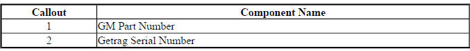
Fig. 47: Identification Tag Marking
SPECIAL TOOLS AND EQUIPMENT
SPECIAL TOOLS
Special tools are used to protect seals, support bearings, install slingers, remove races, hold flanges, and locate noise or leaks accurately. Using the correct tool reduces the risk of damaging new parts during service. Substituting general tools may work in some cases, but it can also distort seals, press bearings incorrectly, or mark precision surfaces.
DT-48074 Input and Output Shaft Seal Installer
DT-48075 Output Shaft Seal Installer
DT-48077 Output Shaft Slinger Installer
DT-48078 Inner Drive Shaft Seal Installer
DT-48094 Inner Drive Shaft Seal Protector
DT-48145 Press Support
J 5590 Pinion Bearing Race Installer - Rear
J 8092 Driver Handle
J-08614-A Pinion Flange Holder and Remover
DT-22912-B
J 22912-B
KM-307-B
Rear Pinion and Axle
Bearing Remover
EL-25070
J 25070
Heat Gun - 500-750
F
DT 26941
J 26941
KM-J 26941
Bushing and Bearing
Remover - 3-4
GE 28431-6
J 28431-6
Fluorescent Oil Dye
6 1-oz
GE 28428-E
J 4220
J 28428-E
High-Intensity Black
Light Kit
EN 29873
J 29873
Injector Nozzle
Socket 30 mm
CH 39570
J 39570
Chassis Ears
DT 45124
J 45124
Removal Bridge