Buick Enclave: Repair Instructions - Off Vehicle
TRANSFER CASE DISASSEMBLE
Off-vehicle transfer case service should be performed on a clean, stable workbench with the unit supported so the housing, machined faces, seals, shafts, and gear components are not damaged during handling. Before disassembly begins, drain any remaining lubricant, clean the exterior of the case, and mark parts where orientation may matter during assembly. For the Buick Enclave Getrag 790 transfer case, careful organization is important because several seals, retainers, shafts, and housing parts look similar but serve different functions.
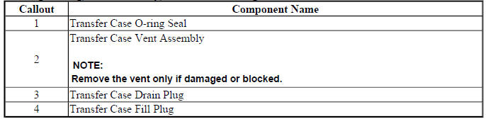
Housing O-ring, Vent Assembly, Drain and Fill Plug Removal
The housing O-ring, vent assembly, drain plug, and fill plug should be removed only after the outside of the transfer case has been cleaned. Dirt around plugs and vents can fall into the housing once components are opened. Inspect the plugs for thread damage, rounded tool surfaces, worn sealing faces, or metal buildup that may indicate internal wear.
Fig. 27: View Of Transfer Case Housing O-Ring, Vent Assembly, Drain & Fill
Plugs
Housing O-Ring, Vent Assembly, Drain and Fill Plug Removal
When removing the vent assembly, avoid twisting or damaging the vent passage. A blocked or damaged vent can cause internal pressure buildup and may lead to repeat leaks after the transfer case is installed. The housing O-ring should not be reused if it has been compressed, cut, flattened, swollen, hardened, or contaminated by the wrong fluid.
Intermediate Drive Shaft Removal
The intermediate drive shaft must be removed carefully so the shaft surface, seal contact area, bearing surfaces, and snap ring groove are not damaged. Before removal, note how the shaft is positioned in the case and check for signs of movement, scoring, corrosion, or oil leakage around the related seals.
Fig. 28: Identifying Intermediate Drive Shaft
Intermediate Drive Shaft Removal
Remove retaining components in the proper order and keep them grouped with the shaft. Do not pry against machined sealing surfaces. If the shaft resists removal, check for a snap ring, bearing retainer, corrosion, or internal bind rather than forcing the component out of the housing.

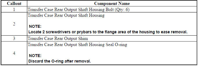
Rear Output Shaft Housing Removal
The rear output shaft housing should be removed squarely from the case to protect the housing bore, O-ring surface, and shaft seal area. Before separation, look for fluid trails, dirt accumulation, or stains around the housing joint. These marks can help identify the original leak path before the parts are cleaned.
Fig. 29: View Of Rear Output Shaft Housing
Rear Output Shaft Housing Removal
Once the housing is removed, inspect the O-ring groove, sealing land, rear output shaft surface, and fastener holes. Any burrs, corrosion, or damage on these areas can cut a new seal or prevent the housing from seating evenly during reassembly.
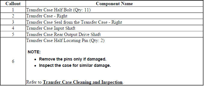
Right Transfer Case, Input and Output Drive Shaft Removal
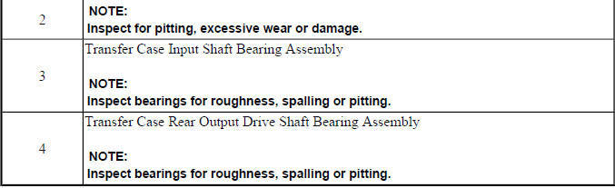
The right transfer case section, input shaft, and output drive shaft should be handled as precision driveline components. Before removal, check for bearing noise evidence, abnormal gear wear, cracked housing areas, metal contamination, or seals that have failed because of shaft movement or surface damage.
Fig. 30: Identifying Right Transfer Case, Input & Output Drive Shaft
Right Transfer Case, Input and Output Drive Shaft Removal
Separate the parts without mixing thrust washers, retainers, bearings, or shaft-related hardware. If gear teeth show pitting, spalling, overheating marks, or unusual contact patterns, inspect the mating gear and bearing support areas before deciding which parts can be reused.
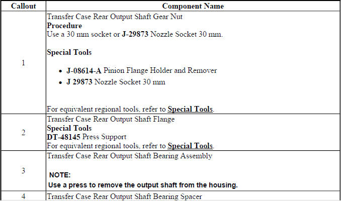
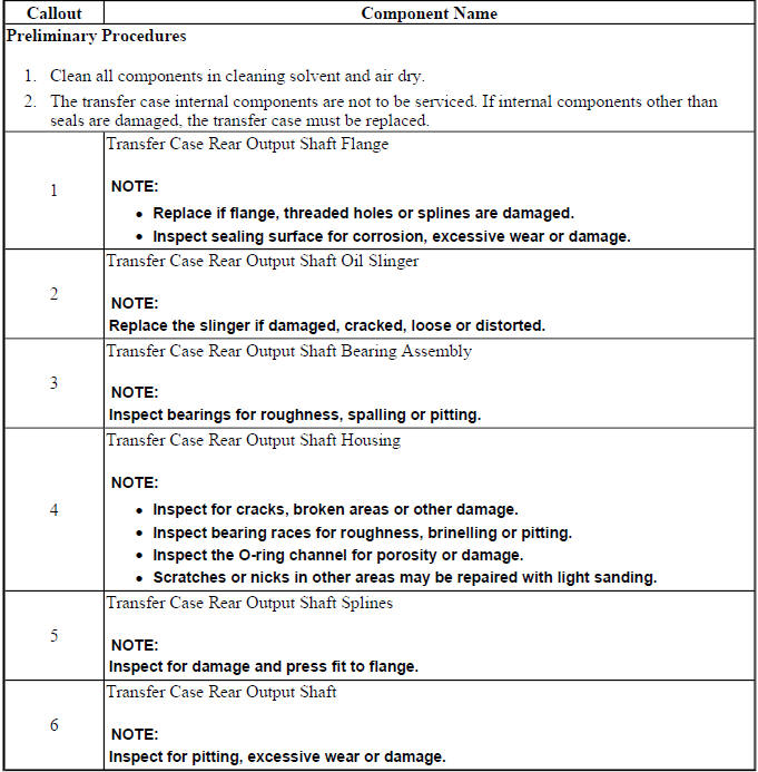
Rear Output Shaft Housing Disassembly
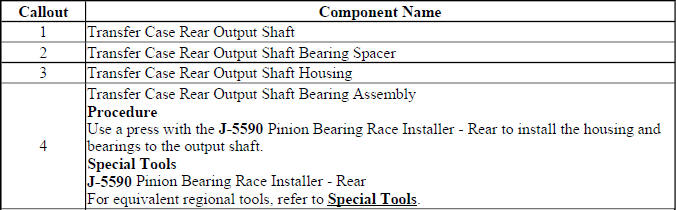
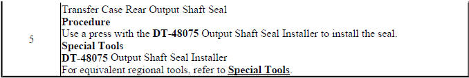
Rear output shaft housing disassembly should be done with the housing supported evenly. The seal, bearing, flange-related components, slinger, and retaining parts should be removed in a controlled order. Do not drive components out with uneven force, because the housing bore can be damaged or distorted.
Fig. 31: Exploded View Of Rear Output Shaft Housing
Rear Output Shaft Housing Disassembly
During disassembly, look at the seal lip contact surface and the bearing fit in the housing. A new seal may not correct a leak if the flange surface is grooved, the bearing has excessive play, or the housing bore is damaged. Keep all small retainers and slingers in order so their direction can be matched during assembly.

Intermediate Drive Shaft Disassembly
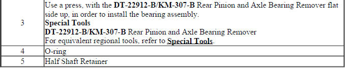
Intermediate drive shaft disassembly includes removal of shaft seals, O-rings, retainers, bearings, and related support parts. Before pressing or removing parts, verify which surface is designed to carry force. Pressing on the wrong race or shoulder can damage a reusable shaft or ruin a new bearing.
Fig. 32: Identifying Intermediate Drive Shaft
Intermediate Drive Shaft Disassembly
After the parts are separated, clean the shaft and inspect the grooves, sealing diameter, splines, bearing journals, and snap ring areas. Any sharp edge near an O-ring groove should be corrected according to service practice, because it can cut the new seal during installation.
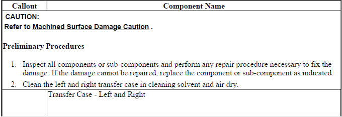
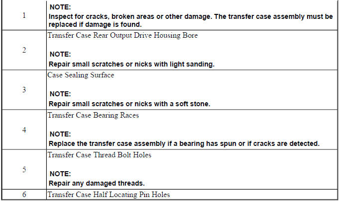
TRANSFER CASE CLEANING AND INSPECTION
Cleaning and inspection are not cosmetic steps. They determine whether the transfer case can be assembled reliably. All passages, machined surfaces, bearing seats, plug threads, seal bores, vents, and gear contact areas should be cleaned and examined before any new parts are installed.
Fig. 33: Identifying Transfer Case Components
Transfer Case Cleaning and Inspection
Use a suitable cleaning method that removes old lubricant, sealant, oxidation, and debris without damaging aluminum surfaces or precision-machined bores. Check the case for cracks, stripped threads, porosity, impact marks, bearing spin, seal bore damage, and signs of overheating. If metallic debris was found in the oil, inspect every bearing and gear contact surface rather than cleaning only the visible area.
REAR OUTPUT DRIVE HOUSING CLEANING AND INSPECTION
The rear output drive housing should be inspected closely because it supports components that affect sealing, shaft alignment, and lubricant control. A housing that looks acceptable from the outside may still have a damaged seal bore, worn bearing seat, or distorted mating surface.
Fig. 34: Exploded View Of Rear Output Drive Housing
Rear Output Drive Housing Cleaning and Inspection
Clean the housing thoroughly, then inspect the seal bore, flange contact area, O-ring groove, bearing support, and fastener holes. If a previous leak was present, identify whether the cause was a failed seal, shaft wear, blocked vent, loose housing, damaged O-ring, or bearing movement. This prevents replacing only the visible seal while leaving the root cause in place.
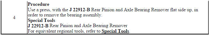
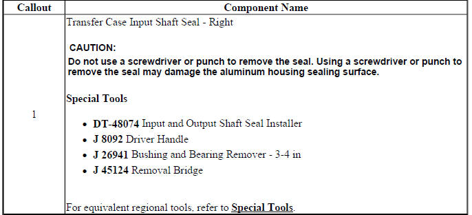
INPUT SHAFT SEAL REPLACEMENT - RIGHT
The right input shaft seal should be replaced with the correct installer and careful attention to seal depth and lip direction. Before installing a new seal, inspect the shaft surface and housing bore. A dry, dirty, grooved, or rusted contact surface can quickly damage the replacement seal.
Fig. 35: Identifying Input Shaft Seal - Right
Input Shaft Seal Replacement - Right
Remove the old seal without scratching the bore. Lightly lubricate the sealing lip where specified and drive the new seal squarely into place. If the seal begins to tilt, stop and correct the alignment rather than forcing it deeper.
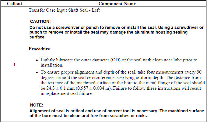
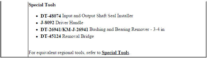
INPUT SHAFT SEAL REPLACEMENT - LEFT
The left input shaft seal is serviced with the same care as the right side, but the surrounding parts and access points may differ. Match the replacement seal to the removed part and verify that the lip faces the correct direction before installation.
Fig. 36: Identifying Input Shaft Seal - Left
Input Shaft Seal Replacement - Left
Clean the bore, check the shaft surface, and install the seal using the proper tool. Uneven installation can distort the shell or roll the lip. After installation, check that the seal sits evenly and that no debris remains near the sealing surface.
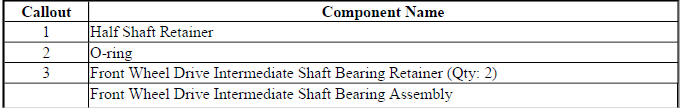
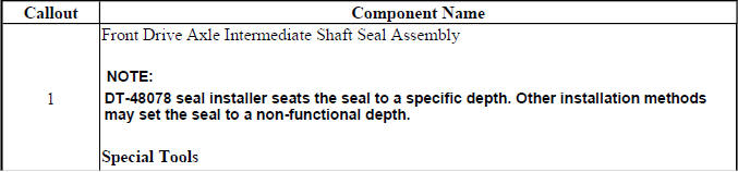
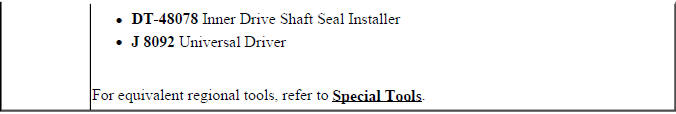
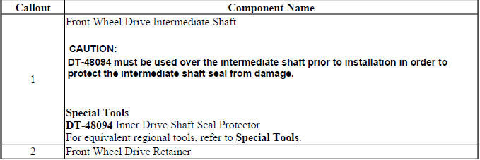
FRONT DRIVE AXLE INNER SHAFT SEAL REPLACEMENT
The front drive axle inner shaft seal prevents lubricant loss at the shaft opening and protects the transfer case from contamination. Before replacing it, inspect the shaft surface, seal bore, and any retainer or guide surface that contacts the seal during assembly.
Fig. 37: Locating Front Drive Axle Inner Shaft Seal
Front Drive Axle Inner Shaft Seal Replacement
Remove the old seal without gouging the housing. Install the new seal squarely and protect the lip from sharp splines or rough edges. A seal protector should be used where required, because even a small cut in the lip can cause a leak shortly after the vehicle returns to service.
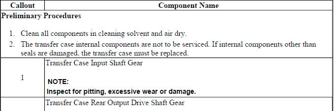
INPUT SHAFT AND REAR OUTPUT DRIVE SHAFT CLEANING AND INSPECTION
The input shaft and rear output drive shaft should be cleaned and inspected before reuse. These shafts affect torque transfer, sealing, bearing support, and driveline smoothness. Damage that is easy to miss on the bench can become a leak, vibration, or noise once the transfer case is loaded in the vehicle.
Fig. 38: Identifying Input Shaft & Rear Output Drive Shaft Components
Input Shaft and Rear Output Drive Shaft Cleaning and Inspection
Check spline condition, bearing journals, seal contact areas, thrust surfaces, gear engagement areas, and any machined shoulders. Look for scoring, pitting, cracks, overheating marks, rough bearing fit, or grooves at the seal contact path. If one shaft shows abnormal wear, inspect the related bearing, gear, housing, and flange before reassembly.
TRANSFER CASE ASSEMBLE
Transfer case assembly should begin only after all parts have been cleaned, inspected, and organized. Replace damaged seals, O-rings, bearings, retainers, and worn components before the case is closed. Assembly lubricant or transfer case fluid should be used only where the procedure specifies it. On a Buick Enclave, rushed assembly can lead to leaks, shaft misalignment, abnormal noise, or repeat transfer case removal.
Intermediate Drive Shaft Assembly
The intermediate drive shaft should be assembled with clean components and correct support. O-rings, retainers, and bearings must be installed in the proper order and orientation. A seal that is rolled or a bearing pressed incorrectly can create a problem before the transfer case is even installed.
Fig. 39: View Of Intermediate Drive Shaft Components
Intermediate Drive Shaft Assembly
Press bearings and retainers using the correct support surfaces. Confirm that each part is fully seated and that the shaft rotates or fits as intended. Before installing the shaft into the case, check for burrs, dirt, or seal damage that could interfere with assembly.

Rear Output Shaft Housing Assembly
Rear output shaft housing assembly requires clean sealing surfaces, correct seal depth, and careful installation of bearings, slingers, and related parts. Before assembly, confirm that the housing bore is clean and that the O-ring groove has no cuts, corrosion, or hardened residue.
Fig. 40: Identifying Rear Output Shaft Housing Components
Rear Output Shaft Housing Assembly
Install the components squarely and avoid striking the housing directly. If a seal or bearing does not move evenly, check tool alignment and housing support before continuing. Proper rear housing assembly helps prevent output flange leaks and bearing noise.
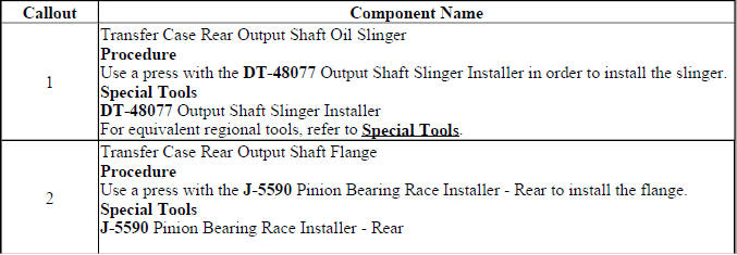
Output Flange Installation
The output flange should be installed only after the seal area, splines, slinger, and mating surfaces have been checked. A flange with a worn seal track or damaged spline area can cause a leak or driveline vibration even if the rest of the transfer case is assembled correctly.
Fig. 41: Exploded View Of Output Flange Components
Output Flange Installation
Install the flange straight and support related parts so the seal lip is not rolled or cut. If the procedure calls for a special installer, use it. Once installed, rotate the flange by hand and feel for drag, roughness, or misalignment before continuing.
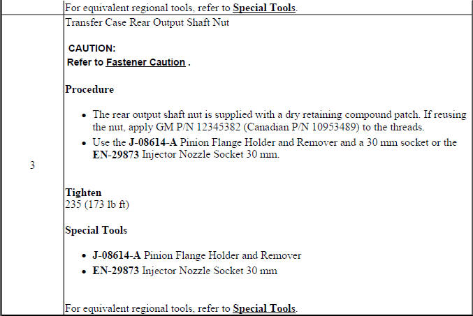
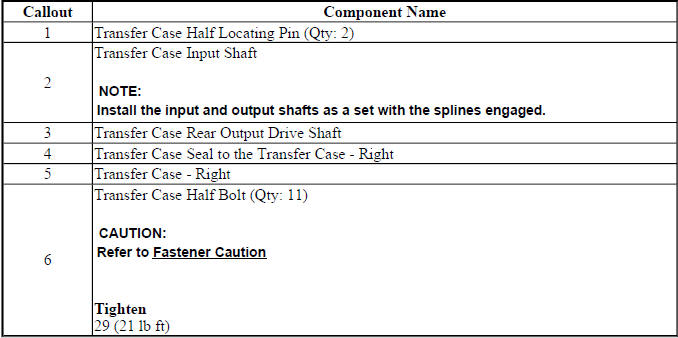
Right Transfer Case, Input Shaft and Output Drive Shaft Installation
When installing the right transfer case section with the input shaft and output drive shaft, keep all rotating parts aligned and clean. The shafts should seat smoothly without forcing. Binding during installation may indicate a misaligned bearing, incorrect part orientation, debris, or a damaged mating surface.
Fig. 42: View Of Right Transfer Case, Input Shaft & Output Drive Shaft
Right Transfer Case, Input Shaft and Output Drive Shaft Installation
Before closing the case, confirm that all internal parts are in place and lubricated where required. Check gear engagement, shaft position, and bearing seating. Do not use housing bolts to force the case together if a gap remains; separate the parts and find the cause.
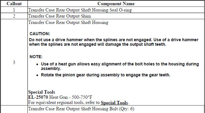
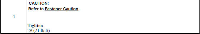
Rear Output Shaft Housing Installation
The rear output shaft housing should be installed with a clean O-ring, clean mating surfaces, and even pressure. Any dirt, hardened sealer, or burrs on the housing face can prevent proper seating and may create a leak path.
Fig. 43: Identifying Rear Output Shaft Housing
Rear Output Shaft Housing Installation
Slide the housing into place squarely and avoid pinching the O-ring. After installation, verify that the housing sits flush and that the output shaft area turns smoothly. Recheck the seal lip position before the transfer case is filled with fluid.
Intermediate Drive Shaft Installation
Intermediate drive shaft installation should be done with the proper tool and seal protection. The shaft must pass through the seal area without cutting or rolling the seal. Make sure the snap ring or retainer system seats fully before the transfer case is placed back into service.
Fig. 44: View Of Intermediate Drive Shaft
Intermediate Drive Shaft Installation
Confirm shaft depth, retainer engagement, and smooth fit after installation. If the shaft does not install cleanly, stop and inspect the O-ring, bearing, snap ring groove, and shaft alignment rather than applying extra force.
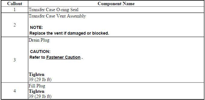
Housing O-Ring, Vent Assembly, Drain and Fill Plug Installation
The final housing O-ring, vent assembly, drain plug, and fill plug installation completes the off-vehicle assembly process. Each sealing point should be clean and correctly positioned. A small error here can cause a leak that may not appear until the transfer case is hot and the lubricant is circulating.
Fig. 45: View Of Transfer Case Housing O-Ring, Vent Assembly, Drain & Fill
Plugs
Housing O-ring, Vent Assembly, Drain and Fill Plug Installation
Install the vent so it can breathe properly and will not be blocked by dirt or sealant. Tighten the drain and fill plugs according to the service procedure and wipe the housing clean for later leak inspection. Once assembled, the transfer case should be ready for on-vehicle installation and final fluid filling.