Buick Enclave: Specifications, Diagnostic Information and Procedures
SPECIFICATIONS
FASTENER TIGHTENING SPECIFICATIONS
Fastener Tightening Specifications
The fastener tightening specifications provide the required torque values for power steering service. These values should be followed carefully during removal and installation because loose, uneven, or over-tightened fasteners can affect steering gear mounting, hose sealing, bracket alignment, and overall steering system reliability.
POWER STEERING PUMP SPECIFICATIONS
Power Steering Pump Specifications

The power steering pump specifications are used to verify pump output, system pressure behavior, and hydraulic performance. When diagnosing a steering concern, these values help separate a weak pump, a restricted line, a faulty steering gear, or a fluid-related issue from a normal operating condition.
SCHEMATIC WIRING DIAGRAMS
POWER STEERING WIRING SCHEMATICS
NV7
Fig. 1: NV7 Wiring Schematics
The NV7 wiring schematic identifies the electrical circuits used by the variable effort steering system. It should be used when tracing high control, low control, connector, actuator, or module-related concerns. A careful review of the schematic before testing helps prevent incorrect probing and reduces the chance of replacing a component when the real fault is in the wiring.
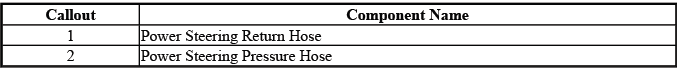
COMPONENT LOCATOR
POWER STEERING GEAR DISASSEMBLED VIEW
Disassembled View
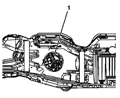
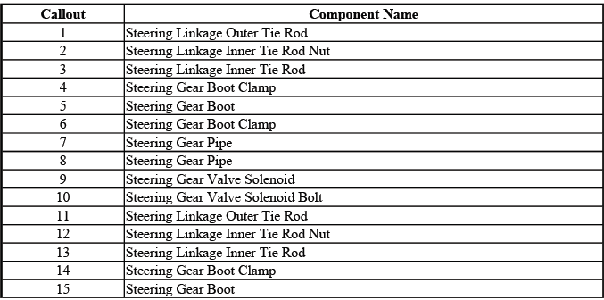

The disassembled views show the steering gear layout, component order, and relationship between the internal and external parts. Use these views as a reference before service work so seals, retainers, housings, and related parts are identified correctly and reinstalled in the proper position.
DIAGNOSTIC INFORMATION AND PROCEDURES
DIAGNOSTIC CODE INDEX
The diagnostic code index helps locate the correct service procedure when a steering-related DTC is stored. Always begin with the code definition, then confirm the circuit, system condition, and scan tool data before replacing parts.
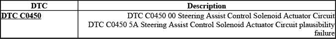
DTC C0450: STEERING ASSIST CONTROL SOLENOID ACTUATOR
Diagnostic Instructions
- Perform the Diagnostic System Check - Vehicle prior to using this diagnostic procedure.
- Review Strategy Based Diagnosis for an overview of the diagnostic approach.
- Diagnostic Procedure Instructions provides an overview of each diagnostic category.
These diagnostic instructions keep the testing process organized. The system check should be completed first because steering assist faults can be affected by module communication, voltage supply, stored history codes, connector condition, or related brake control system inputs.
DTC Descriptors
DTC C0450 00
- Steering Assist Control Solenoid Actuator Circuit
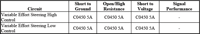
DTC C0450 5A
- Steering Assist Control Solenoid Actuator Circuit plausibility failure
DTC C0450 is associated with the steering assist control solenoid actuator circuit. Depending on the specific descriptor, the system may detect an electrical circuit fault or a plausibility concern where the actuator response does not match the expected command.
Diagnostic Fault Information
Circuit/System Description
The electronic brake control module (EBCM) controls the variable effort steering (VES) actuator mounted on the steering gear. The EBCM regulates the actuator with a current range from 0 to 1.0 amp. At 0 mph, the EBCM supplies approximately 1.0 amp to the actuator to provide the appropriate level of steering assist. As vehicle speed increases, the commanded amperage decreases so the steering feel becomes more controlled at higher speeds.
On the Buick Enclave, this variable effort strategy is used to balance low-speed steering ease with higher-speed stability. If the actuator circuit fails, the steering system may lose the intended assist variation, and the driver may notice a change in steering feel.
Conditions for Running the DTC
- Ignition ON.
- Engine OFF test - Initial ignition ON, no engine RPM or vehicle speed present.
- Engine ON test - If Engine OFF test passes, engine RPM and vehicle speed present.
The diagnostic runs in stages. The module can first evaluate the circuit with the ignition on and the engine off, then continue testing when engine RPM and vehicle speed are present. This helps identify both static circuit faults and operating faults that appear only when the system is active.
Conditions for Setting the DTC
A short to voltage, short to ground, open circuit, or high resistance condition is detected on the high control or low control circuit. Any of these faults can prevent the VES actuator from receiving the correct command or returning the expected electrical response.
Action Taken When the DTC Sets
- The ABS and red brake warning indicators illuminate.
- The driver information center (DIC) displays SERVICE STEERING SYSTEM.
- The VES system is disabled for the remainder of the ignition cycle.
When this DTC sets, the vehicle alerts the driver and disables the variable effort steering function for that ignition cycle. The base steering function may remain available, but the electronically controlled change in steering effort will not operate as intended until the fault is corrected and the system passes its checks.
Conditions for Clearing the DTC
- A current DTC will clear when the malfunction is no longer present.
- A history DTC will clear after 100 consecutive ignition cycles with the malfunction no longer present.
After repairs are completed, the current fault should clear once the module no longer detects the malfunction. A history code remains stored until the required number of fault-free ignition cycles has passed, unless it is cleared with an appropriate scan tool during service.
Reference Information
Schematic Reference
Power Steering Schematics
Connector End View Reference
COMPONENT CONNECTOR END VIEWS - INDEX
Description and Operation
Variable Effort Steering System Description and Operation
Electrical Information Reference
- Circuit Testing
- Connector Repairs
- Testing for Intermittent Conditions and Poor Connections
- Wiring Repairs
Scan Tool Reference
Control Module References for scan tool information
The reference information should be used together rather than separately. The schematic shows circuit routing, connector end views confirm terminal locations, electrical repair procedures explain proper testing methods, and scan tool references identify the module controls and data needed to complete the diagnosis.
Circuit/System Verification
With the engine running, use a scan tool to perform the VES Actuator test. Command the actuator while turning the steering wheel. Steering effort should increase when the actuator is commanded between 10-100%. A clear change in effort confirms that the actuator and control circuit are responding to scan tool commands.
If the steering effort does not change, do not assume the actuator has failed immediately. Confirm power, ground, control circuit integrity, connector fit, terminal tension, and scan tool command response before replacing the actuator or EBCM.
Circuit/System Testing
1. Ignition OFF, disconnect the harness connector at the VES actuator. Inspect the connector before testing. Look for loose terminals, corrosion, moisture, damaged locks, spread pins, or wiring strain near the connector body.
2. Ignition ON, command the VES actuator to 100% with a scan tool. This places the circuit in a commanded state so voltage and control response can be checked accurately.
3. Test for B+ between the high control circuit terminal 2 and ground.
- If not the specified value, test the high control circuit for a short to ground or an open/high resistance. If the circuit tests normal, replace the EBCM.
4. Connect a DMM, set on the diode setting, between the low control circuit terminal 1 and ground. Make sure the meter leads have a secure connection and do not spread the terminals during testing.
5. Command the VES actuator to 0% with a scan tool. The DMM reading should be greater than 2.5 volts or display O.L.
- If less than the specified value, test the low control circuit for a short to voltage or a short to ground. If the circuit tests normal, replace the EBCM.
6. Command the VES actuator to 100% with a scan tool. The DMM reading should be less than 1 volt.
- If greater than the specified range, test the low control circuit for an open/high resistance. If the circuit tests normal, replace the EBCM.
7. If all circuits test normal, test or replace the VES actuator. Before replacement, verify that the connector fits tightly and that the actuator is not affected by contamination, physical damage, or poor mounting at the steering gear.
Component Testing
1. Ignition OFF, disconnect the harness connector at the VES actuator. The actuator should be isolated from the vehicle circuit before resistance checks are performed.
2. Test for 5-10 ohms between the control terminals 1 and 2.
- If not within the specified range, replace the VES actuator.
3. Test for infinite resistance between each terminal and the VES actuator housing/case.
- If not the specified value, replace the VES actuator.
These resistance checks help identify an internal open, shorted winding, or short to the actuator housing. Use a reliable meter and clean test leads so the readings are not affected by poor contact at the terminals.
Repair Instructions
Perform the Diagnostic Repair Verification after completing the diagnostic procedure. Verification confirms that the fault has been corrected and that the steering assist system operates normally under the same conditions that originally produced the concern.
- Steering Gear Replacement
- Control Module References for EBCM replacement, setup and programming
SYMPTOMS - POWER STEERING SYSTEM
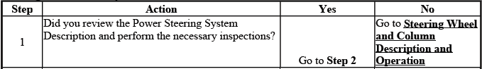
IMPORTANT: Review the system description and operation in order to familiarize yourself with the system functions. Refer to Power Steering System Description and Operation.
Visual/Physical Inspection
- Inspect for aftermarket devices which could affect the operation of the power steering system.
- Inspect the easily accessible or visible system components for obvious damage or conditions which could cause the symptom.
- Inspect for leaking power steering components. If necessary, refer to Power Steering Fluid Leaks.
- Verify the power steering reservoir for the proper operating specification. Refer to Checking and Adding Power Steering Fluid.
- Inspect the power steering fluid for the following indications of contamination:
- Milky fluid - water
- Brown fluid - burnt
- Debris in fluid - plastic or dirt
- If necessary, flush the power steering system. Refer to Power Steering System Flushing.
Begin symptom diagnosis with a visual and physical inspection. Many power steering problems are caused by low fluid level, aerated fluid, leaks, damaged hoses, incorrect routing, loose brackets, aftermarket electrical devices, or contamination in the reservoir. A simple inspection can prevent unnecessary steering gear or pump replacement.
Fluid condition is especially important. Milky fluid may indicate water contamination, brown or dark fluid can point to heat damage, and visible debris may suggest internal wear or contamination from rubber, plastic, or dirt. If the system is contaminated, flushing may be required before accurate diagnosis can continue.
Symptoms List
Refer to a symptom diagnostic procedure from the following list in order to diagnose the symptom:
- Power Steering Fluid Leaks
- Rattle, Clunk or Shudder Noise from the Power Steering System
- Whine or Growl Noise from the Power Steering System
- Steering Effort Hard in One or Both Directions
- Steering Effort Too Easy in One or Both Directions
Select the symptom that best matches the customer concern. A noise complaint, a steering effort complaint, and a leak complaint may require different tests, even when they appear to involve the same power steering components.
POWER STEERING SYSTEM TEST
Rack and Pinion System
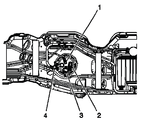
Fig. 3: Testing Rack and Pinion System Pressures
Test Description
The numbers below refer to the step numbers on the diagnostic table. Each step isolates a different part of the hydraulic power steering system, including restrictions, pump output, flow regulation, internal leakage, and steering gear performance.
5
This step tests the system for restrictions. A restriction can be caused by a kinked hose, collapsed internal hose lining, blocked cooler, contaminated fluid passage, or a damaged fitting.
7
This step tests the following components for the following conditions:
- The pump for internal leaks
- The power steering pipes for kinks
A pump with internal leakage may not build pressure correctly, while kinked or restricted pipes can prevent the required flow from reaching the steering gear.
8
This step tests the ability of the pump to regulate flow at maximum pressure. The result helps determine whether the pump can support the steering system during high-load conditions such as low-speed turning.
10
This step tests the ability of the pump to regulate flow under normal operating conditions. A pump may pass a basic pressure check yet still show poor flow control during normal steering operation.
12
This step tests the internal components of the pump and the gear. If earlier checks are normal but the symptom remains, internal leakage or wear inside the pump or rack and pinion gear may be present.
Power Steering System Test
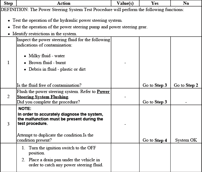
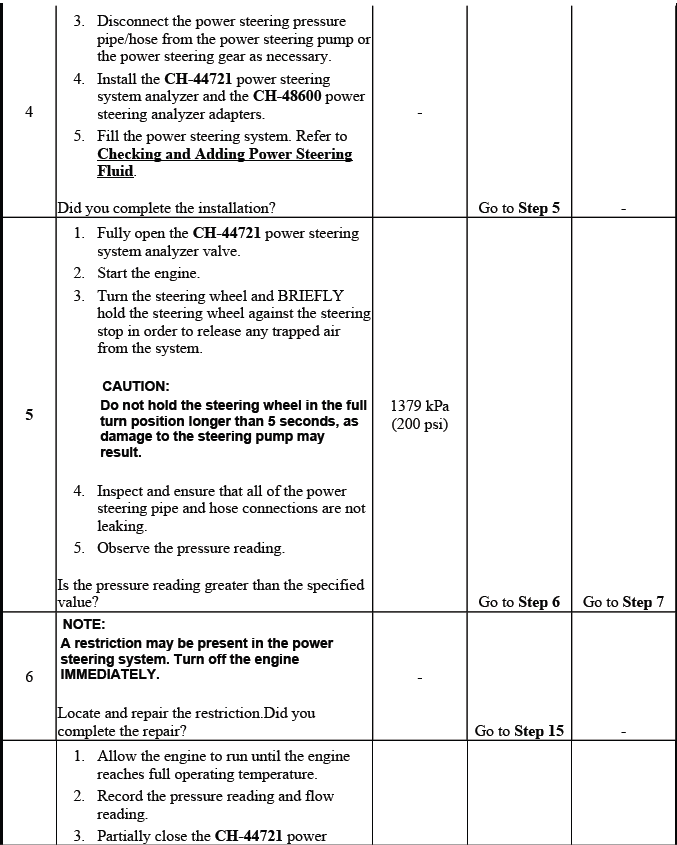
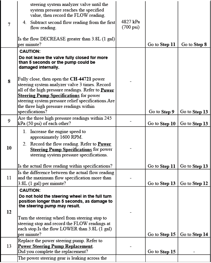
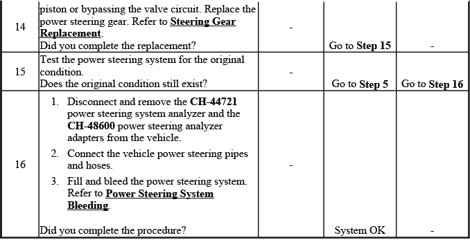
During the power steering system test, follow the pressure and flow checks in order. Skipping steps can lead to a false diagnosis because a weak pump, a restricted hose, contaminated fluid, or an internally leaking steering gear may create similar steering effort symptoms.
POWER STEERING FLUID LEAKS
Special Tools
- GE-28431-6 Fluorescent Dye
For equivalent regional tools, refer to Special Tools.
NOTE:
- If fluid is found on a manual steering gear or on an electronic power steering gear, do not replace steering gear. Vehicles equipped with these systems do not use hydraulic power steering fluid. The fluid may be assembly fluid or another system fluid.
- Clean the components and identify the sources of the leaks before attempting to repair or replace any power steering components. Clearly mark all locations of leaks with paint, marker or equivalent for warranty identification and engineering root cause analysis.
Some customers may comment on a fluid leak or a noisy power steering pump. During inspection, the technician may find fluid on or near components in the hydraulic power steering system. Use the following procedure to confirm whether the fluid is actually power steering fluid, locate the source of the leak, and choose the correct repair.
1. Inspect the fluid level in the power steering fluid reservoir. Refer to Checking and Adding Power Steering Fluid. If the fluid level is not low, analyze the condition carefully before assuming that the fluid is power steering fluid. Other fluids can travel along brackets, hoses, covers, or frame surfaces and collect near the steering system.
2. Visually inspect the power steering system and the components where the fluid has accumulated. Look above and around the wet area, because a leak often runs downward or rearward before it becomes visible.
3. Use a clean towel or rag to completely clean all residual fluid from the power steering components. The surface must be clean enough for a fresh leak trace to be identified clearly.
CAUTION: Do not clean using brake cleaner or other reactive solvents as these solvents can damage rubber gaskets, seals and bushings.
4. Add 30 cc (1 oz) of GE-28431-6 dye to the power steering fluid. The dye helps identify the actual source of leakage under a black light.
5. Start the vehicle and warm the steering system by turning to the left steering stop and to the right steering stop 10 times with the weight of the vehicle on the front tires. Do not hold the steering wheel hard against the stops longer than necessary, as this can raise pressure and temperature in the hydraulic system.
6. Turn the vehicle engine OFF. Allow the components to settle briefly so fresh leakage can be seen without moving parts or splashing fluid.
7. Shine a black light on the area where the residual fluid accumulated. Identify the source of the leak by following the fluorescent trace back to its highest or earliest visible point.
8. Mark all leak locations with paint, marker, or equivalent. Marking the source helps document the repair and prevents confusion if fluid spreads during handling.
9. Repair or replace all affected components. After repair, clean the area again, refill the system as needed, bleed or cycle the steering system if required, and confirm that no fresh leak appears.
RATTLE, CLUNK OR SHUDDER NOISE FROM THE POWER STEERING SYSTEM
Rattle, Clunk or Shudder Noise from the Power Steering System
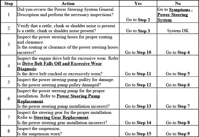
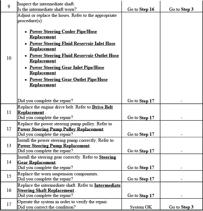
A rattle, clunk, or shudder may come from the steering gear, intermediate shaft, pump, hoses, mounting points, suspension components, or fluid condition. Confirm when the sound occurs: parking maneuvers, steering reversal, low-speed turns, bumps, engine idle, or throttle changes. The condition should be duplicated before parts are removed.
WHINE OR GROWL NOISE FROM THE POWER STEERING SYSTEM
Whine or Growl Noise from the Power Steering System

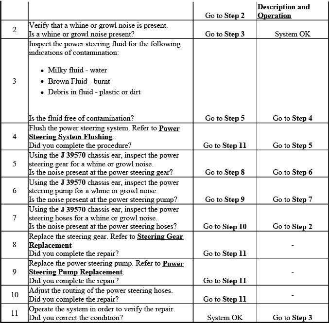
A whine or growl often points toward low fluid level, aerated fluid, pump wear, restriction, contamination, or excessive system load. If the noise changes when the steering wheel is turned, inspect fluid level, fluid condition, hose routing, pump inlet restrictions, and the steering gear before replacing the pump.
STEERING EFFORT TOO EASY IN ONE OR BOTH DIRECTIONS
Steering Effort Too Easy in One or Both Directions
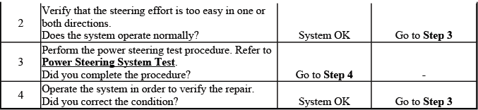
Steering effort that feels too easy may indicate over-assist, incorrect variable effort steering response, steering gear concerns, speed signal issues, or a control-related fault. Compare effort at low speed and road speed, and check whether the condition affects one direction or both directions.
STEERING EFFORT HARD IN ONE OR BOTH DIRECTIONS
Steering Effort Hard in One or Both Directions
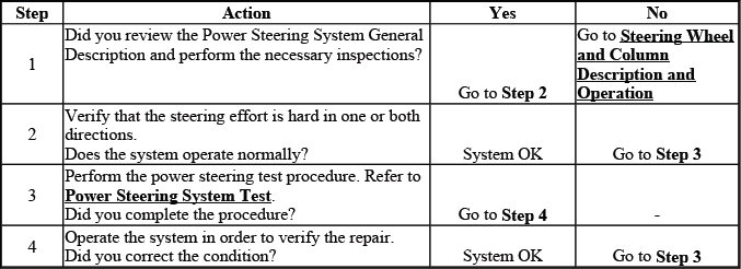
Hard steering effort may be caused by low fluid, air in the hydraulic system, pump weakness, a restricted line, steering gear internal binding, belt drive issues, suspension binding, or VES-related faults. Determine whether the hard effort occurs in one direction, both directions, only at idle, only when hot, or during all driving conditions. This pattern is often the fastest way to narrow the cause.
