Buick Enclave: Specifications, Diagnostic Information and Procedures
SPECIFICATIONS
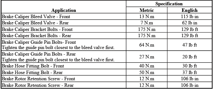
FASTENER TIGHTENING SPECIFICATIONS
Fastener Tightening Specifications
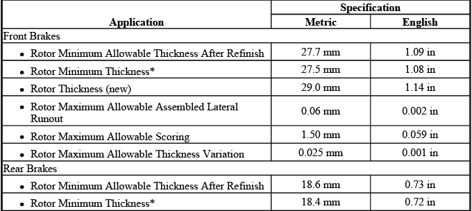
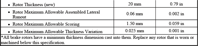
DISC BRAKE COMPONENT SPECIFICATIONS
General Specifications
DIAGNOSTIC INFORMATION AND PROCEDURES
BRAKE ROTOR THICKNESS MEASUREMENT
WARNING: Refer to Brake Dust Warning. Brake dust should be handled carefully, and the rotor area should be cleaned using approved methods rather than blown out with compressed air.
1. Clean the brake pad lining contact surface of the brake rotor with denatured alcohol or an equivalent approved brake cleaner. The surface must be free of loose rust, dirt, grease, and brake residue before an accurate thickness measurement can be taken.
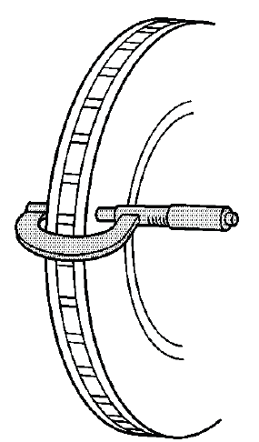
Fig. 1: Measuring Brake Rotor Thickness
2. Using a micrometer calibrated in ten-thousandths of a millimeter or ten-thousandths of an inch, measure and record the lowest thickness of the brake rotor at four or more points, equally spaced around the rotor. Taking measurements at several locations helps identify uneven wear that may not be visible during a quick surface inspection.
Ensure that the measurements are taken only within the brake pad lining contact area and that the micrometer is positioned the same distance from the outside edge of the rotor for each measurement. Keeping the measuring location consistent is important because rotor thickness can vary from the inner edge to the outer edge of the friction surface.
3. Compare the lowest thickness measurement recorded to the specifications. Refer to Disc Brake Component Specifications. The lowest reading is the deciding value because the rotor must remain serviceable at its thinnest usable point, not just at the average thickness.
4. If the lowest thickness measurement of the brake rotor is above the brake rotor minimum thickness specification, the rotor may be refinished, depending upon the surface and wear conditions which may be present. Before refinishing, confirm that enough material will remain after machining and that the rotor does not show damage that would make reuse unsuitable.
5. If the lowest thickness measurement of the brake rotor is below the minimum thickness specification, the rotor requires replacement. A rotor that is too thin may overheat more easily, may not absorb braking heat properly, and may reduce braking consistency during repeated stops.
BRAKE ROTOR THICKNESS VARIATION MEASUREMENT
WARNING: Refer to Brake Dust Warning. Use safe cleaning procedures when working around the rotor, caliper, and brake pad area.
NOTE: Any disc brake rotor that exhibits thickness variation exceeding the maximum acceptable level must be refinished or replaced. Thickness variation exceeding the maximum acceptable level can cause brake pulsation, especially when the brakes are applied at highway speed or during moderate pedal pressure.
1. If the inboard friction surface of the brake rotor is not accessible, reposition and support the caliper with the brake pads. Refer to Front Disc Brake Pads Replacement and/or Rear Disc Brake Pads Replacement. Do not allow the caliper to hang by the brake hose, because hose strain can lead to damage or internal restriction.
2. Clean the friction surfaces of the brake rotor with denatured alcohol or an equivalent approved brake cleaner. A clean surface helps the micrometer jaws contact the metal evenly and reduces the chance of a false reading caused by debris or residue.
3. Using a micrometer (1) calibrated in thousandths-of-a-millimeter or ten-thousandths-of-an-inch, measure and record the thickness of the brake rotor at 4 or more points, evenly spaced around the rotor. On the Buick Enclave, this measurement is important when diagnosing brake pedal pulsation, steering wheel shake during braking, or uneven braking feel.
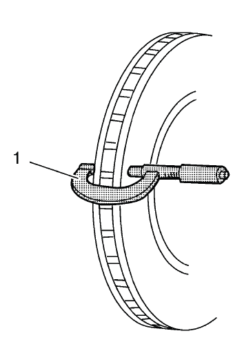
Fig. 2: Micrometer On Brake Rotor
Ensure that the measurements are only taken within the friction surfaces and that the micrometer is positioned the same distance from the outer edge of the rotor, about 13 mm (1/2 in), for each measurement. Moving the micrometer inward or outward between readings can create misleading results.
4. Calculate the difference between the highest and lowest thickness measurements recorded to obtain the amount of thickness variation. This value shows how much the rotor thickness changes as it rotates through the brake pads.
5. Compare the thickness variation measurement to the following specification:
Specification
Brake rotor maximum allowable thickness variation: 0.025 mm (0.001 in)
6. If the brake rotor thickness variation measurement exceeds the specification, the rotor requires refinishing or replacement. A rotor with excessive variation can push the pads and caliper piston back and forth during braking, creating a pulsation that may be felt through the brake pedal.
NOTE: Whenever a brake rotor is refinished or replaced, the assembled lateral runout (LRO) of the rotor must be measured to ensure optimum performance of the disc brakes. Rotor thickness variation and lateral runout are closely related service checks, and ignoring one can allow a brake pulsation concern to return after repair.
BRAKE ROTOR SURFACE AND WEAR INSPECTION
WARNING: Refer to Brake Dust Warning. Avoid breathing dust from the brake assembly and clean the work area with approved brake cleaning methods.
1. If the inboard friction surface of the brake rotor is not accessible, reposition and support the caliper with the brake pads. Refer to Front Disc Brake Pads Replacement and/or Rear Disc Brake Pads Replacement. Supporting the caliper correctly prevents brake hose stress and gives a clear view of both rotor friction surfaces.
2. Clean the friction surfaces of the brake rotor with denatured alcohol or an equivalent approved brake cleaner. Inspection should be performed only after the rotor surface is clean enough to show wear marks, heat damage, cracks, or surface pitting clearly.
3. Inspect the friction surfaces of the brake rotor for the following Braking Surface Conditions:
- Heavy rust and/or pitting
Light surface rust can usually be removed with an abrasive disc. Heavy surface rust and/or pitting must be removed by refinishing the rotor if the rotor remains within service limits after machining. If the rust or pitting is too deep, replacement is the safer repair choice.
- Cracks and/or heat spots
- Excessive blueing discoloration
Cracks, heat checking, dark hot spots, or strong blue discoloration can indicate that the rotor has been exposed to excessive heat. This may be caused by aggressive braking, a sticking caliper, restricted brake hose, seized guide pin, or brake pads that are not releasing correctly. When inspecting disc brakes on the Buick Enclave, the cause of heat damage should be corrected before new pads or rotors are installed.
Surface condition should always be considered together with rotor thickness, thickness variation, and assembled lateral runout. A rotor may appear acceptable at first glance but still cause brake noise, pedal pulsation, or vibration if the measurements are outside specification. A complete inspection helps prevent repeat brake concerns and ensures the disc brake system performs smoothly after service.
4. If the friction surfaces of the brake rotor show one or more of the listed Braking Surface Conditions, the rotor requires refinishing or replacement. The decision should be based not only on appearance, but also on rotor thickness, scoring depth, heat damage, and whether enough material will remain after machining.
5. Using a micrometer (1) calibrated in thousandths-of-a-millimeter or ten-thousandths-of-an-inch, measure and record the scoring depth of any grooves present on the rotor friction surfaces. Measure the deepest visible grooves rather than shallow surface marks, because deep scoring can reduce pad contact area and may contribute to noise, uneven wear, or reduced braking smoothness.
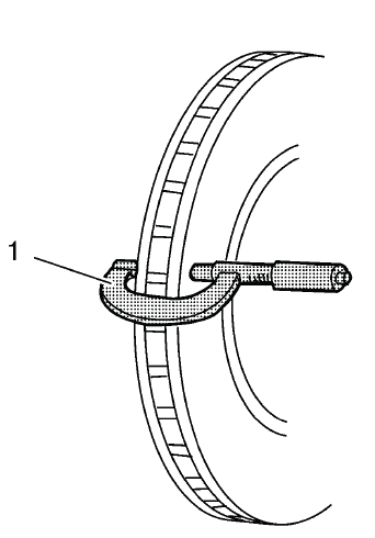
Fig. 3: Micrometer On Brake Rotor
6. Compare the recorded groove scoring depth to the following specification. The measurement should be taken carefully, with the micrometer positioned squarely on the rotor surface so the reading reflects the true depth of the groove.
Specification
- Brake rotor maximum allowable scoring: 1.50 mm (0.059 in)
7. If the brake rotor scoring depth exceeds the specification or if an excessive amount of scoring is present across the friction surface, the rotor requires refinishing or replacement. On the Buick Enclave, a heavily scored rotor should not be reused simply because the brake pads still have remaining material; the rotor surface must be able to provide stable, even contact with the pads.
BRAKE ROTOR ASSEMBLED LATERAL RUNOUT MEASUREMENT
Special Tools
- CH-41013 Rotor Resurfacing Kit
- CH-42450-A Wheel Hub Resurfacing Kit
- CH-45101 Hub and Wheel Runout Gauge
- CH-45101-100 Conical Brake Rotor Washers
For equivalent regional tools, refer to Special Tools. Equivalent tools must be capable of holding the rotor evenly against the hub and measuring runout accurately at the specified location on the friction surface.
WARNING: Refer to Brake Dust Warning. Brake dust should be handled with proper cleaning methods, and the brake area should not be cleaned by blowing dust into the air.
NOTE:
- Brake rotor assembled lateral runout (LRO) exceeding the maximum allowable specification can cause thickness variation to develop in the brake rotor over time, usually between 4,800-11,300 km (3,000-7,000 mi). This is one of the common reasons a brake pulsation may return after a rotor has been replaced or refinished.
- Brake rotor thickness variation MUST be checked BEFORE checking for assembled lateral runout (LRO). Thickness variation exceeding the maximum acceptable level can cause brake pulsation. Refer to Brake Rotor Thickness Variation Measurement. Checking runout before confirming thickness variation can lead to an incomplete diagnosis.
1. Matchmark the position of the brake rotor to the wheel studs if this has not been done already. This mark helps preserve the original rotor-to-hub position and gives a reference point if the rotor must be indexed during runout correction.
2. Inspect the mating surface of the hub/axle flange and the brake rotor to ensure that there are no foreign particles, corrosion, rust, scale, or debris remaining. Even a small amount of material trapped between the rotor and hub can prevent the rotor from sitting flat and may create excessive assembled lateral runout. If the wheel hub/axle flange and/or the brake rotor mating surfaces exhibit these conditions, perform the following steps:
NOTE: Whenever the brake rotor has been separated from the hub/axle flange, any rust or contaminants should be cleaned from the hub/axle flange and the brake rotor mating surfaces. Failure to do this may result in excessive assembled lateral runout (LRO) of the brake rotor, which could lead to brake pulsation. This step is especially important when diagnosing repeat pulsation concerns after previous brake service.
- Remove the brake rotor from the vehicle. Refer to Front Brake Rotor Replacement and/or Rear Brake Rotor Replacement.
- Using the CH-42450-A wheel hub resurfacing kit, thoroughly clean any rust or corrosion from the mating surface of the hub/axle flange. The cleaned hub surface should be smooth enough to allow the rotor to sit flush without rocking or high spots.
- Using the CH-41013 rotor resurfacing kit, thoroughly clean any rust or corrosion from the mating surface of the brake rotor. Do not remove unnecessary metal from the rotor hat; the goal is to remove corrosion and contamination from the contact area.
- Clean the friction surfaces of the brake rotor with denatured alcohol or an equivalent approved brake cleaner. This removes residue left from handling or cleaning and helps prepare the rotor for accurate measurement.
3. Install the rotor to the hub/axle flange using the matchmark made prior to removal. Make sure the rotor seats fully against the hub before installing the holding washers and lug nuts.
4. Hold the rotor firmly in place against the hub/axle flange and install one of the CH-45101-100 conical brake rotor washers (1) and one lug nut (2) onto the upper-most wheel stud. The conical washer helps simulate wheel clamping force so the rotor is held in a realistic installed position during measurement.
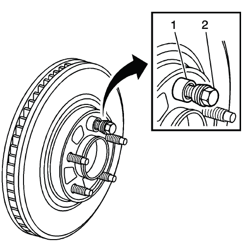
Fig. 4: Identifying Special Tool J 45101-100 & Lug Nut
5. Continue to hold the rotor secure and tighten the lug nut firmly by hand. The rotor should remain flat against the hub face and should not shift while the remaining washers and lug nuts are installed.
6. Install the remaining CH-45101-100 conical brake rotor washers and lug nuts onto the wheel studs and tighten the nuts firmly by hand in a star-pattern. This pattern applies clamping force evenly and helps avoid distorting the rotor during setup.
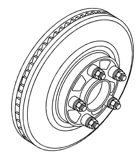
Fig. 5: Identifying All Special Tools J 45101-100s & Lug Nuts
7. Tighten the lug nuts in a star-pattern to specification. Refer to Tire and Wheel Removal and Installation. Correct tightening is necessary because uneven or loose clamping can change the runout reading and lead to a false diagnosis.
8. If the brake rotor has been REFINISHED or REPLACED with a new rotor, proceed to step 14. A newly machined or replacement rotor still requires assembled runout verification because hub condition and mounting alignment can affect the final installed measurement.
9. If the brake rotor meets the following criteria, proceed to step 10.
- The rotor is within specifications and is being REUSED.
- The rotor has NOT been refinished.
- The rotor does NOT exhibit thickness variation exceeding the maximum allowable level.
10. Mount a dial indicator, CH-45101 hub and wheel runout gauge or equivalent, to the steering knuckle and position the indicator button so it contacts the brake rotor friction surface at a 90 degree angle, approximately 13 mm (0.5 in) from the outer edge of the rotor. The indicator must be mounted securely so vibration, tool movement, or an angled contact point does not affect the reading.
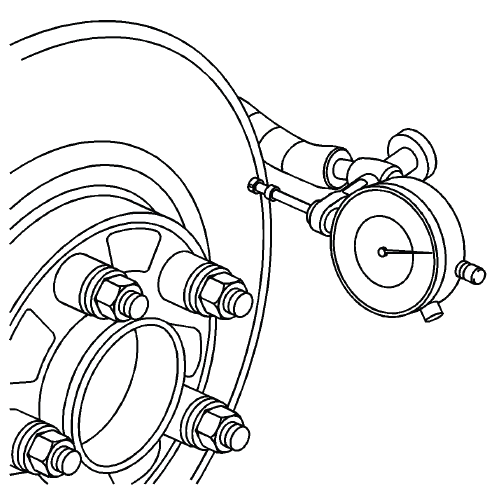
Fig. 6: Using Dial Indicator To Measure Lateral Runout
When measuring assembled lateral runout on the Buick Enclave, rotate the rotor slowly and watch the full indicator sweep rather than relying on a single point. Accurate LRO measurement helps prevent repeat brake pedal pulsation, uneven pad transfer, and premature rotor thickness variation after service.
11. Measure and record the assembled LRO of the brake rotor. Rotate the rotor slowly and watch the dial indicator movement through a full revolution so the total amount of lateral movement can be identified accurately.
- Rotate the rotor until the lowest reading is displayed on the indicator dial, then set the dial to zero. This establishes the reference point for the measurement.
- Rotate the rotor until the highest reading is displayed on the dial. Move the rotor smoothly so the indicator button does not jump or give a false reading.
- Mark the location of the high spot relative to the nearest wheel stud or studs. This mark is important if the rotor position needs to be corrected or compared later.
- Measure and record the amount of LRO. The final reading should represent the difference between the lowest and highest dial indicator positions.
12. Compare the brake rotor assembled LRO to the following specification. The value must be checked against the correct front or rear rotor limit before deciding whether the rotor can remain in service.
Specification
- Front brake rotor maximum allowable assembled lateral runout: 0.05 mm (0.002 in)
- Rear brake rotor maximum allowable assembled lateral runout: 0.05 mm (0.002 in)
13. If the brake rotor assembled LRO is within specifications, proceed to step 18.
If the brake rotor assembled LRO exceeds the specification, refinish the rotor to ensure true parallelism. Excessive runout can lead to uneven pad contact, brake pedal pulsation, and rotor thickness variation after the vehicle has been driven for a period of time.
Refer to Brake Rotor Refinishing. After refinishing the rotor, proceed to step 14. On the Buick Enclave, this verification step is important because a freshly machined or replaced rotor can still show excessive runout if the hub surface, rotor seating, or clamping force is not correct.
14. Mount a dial indicator, CH-45101 hub and wheel runout gauge or equivalent, to the steering knuckle and position the indicator button so it contacts the brake rotor friction surface at a 90º angle, approximately 13 mm (0.5 in) from the outer edge of the rotor. Make sure the indicator base is secure and that the contact point remains stable while the rotor is turned.
15. Measure and record the assembled LRO of the brake rotor. Use the same method and measuring location each time so the results can be compared accurately.
- Rotate the rotor until the lowest reading is displayed on the indicator dial, then set the dial to zero.
- Rotate the rotor until the highest reading is displayed on the dial.
- Mark the location of the high spot relative to the nearest wheel stud or studs. This helps identify whether the high spot follows the rotor or remains related to the hub position.
- Measure and record the amount of LRO. Record the reading before loosening any hardware or changing rotor position.
16. Compare the brake rotor assembled LRO to the following specification:
Specification
- Front brake rotor maximum allowable assembled lateral runout: 0.05 mm (0.002 in)
- Rear brake rotor maximum allowable assembled lateral runout: 0.05 mm (0.002 in)
17. If the brake rotor assembled LRO measurement exceeds the specification, bring the LRO to within specifications. Refer to Brake Rotor Assembled Lateral Runout Correction. Do not skip this correction, because installing new pads on a rotor with excessive runout can allow a brake pulsation complaint to return.
18. If the brake rotor assembled LRO measurement is within specification, install the brake caliper and depress the brake pedal several times to secure the rotor in place before removing the CH-45101-100 conical brake rotor washers and the lug nuts. Pressing the brake pedal seats the pads against the rotor and helps hold the rotor in the correct installed position during final assembly.
BRAKE PAD INSPECTION
1. Inspect the disc brake pads at regular intervals or whenever the tire and wheel assemblies are removed from the vehicle. A visual inspection during wheel service can reveal early signs of uneven wear, noise-related damage, or caliper movement problems before they become more serious.
Fig. 7: View Of Brake Pads & Audible Wear Sensors
WARNING: Refer to Brake Dust Warning. Use approved brake cleaning methods and avoid breathing dust from the pad and rotor area.
2. If replacement is necessary, always replace disc brake pads in axle sets. Replacing pads on only one side of an axle can create uneven braking force, brake pull, or inconsistent pedal feel.
3. Inspect both edges of the disc brake pad friction surfaces (3). The highest rate of wear normally occurs at the trailing edge of the disc brake pads. A noticeable difference between the leading and trailing edges may point to caliper slide binding, pad drag, or poor bracket hardware condition.
4. Inspect the thickness of the disc brake pads (3) in order to ensure that they have not worn prematurely. Check the inner and outer pads carefully, because the inner pad can wear faster when a caliper piston or slide mechanism is not releasing properly.
The disc brake pad wear should be approximately even per axle set. On the Buick Enclave, uneven pad wear across one axle should be investigated before new pads are installed, since the cause may be related to guide pins, pad hardware, caliper movement, or rotor surface condition.
5. Both front and rear disc brake pads have integral, audible wear sensors (1). When the disc brake pad wear reaches the minimum allowable thickness, the wear sensor contacts the disc brake rotor (2). The wear indicator will then produce an audible, high-pitched warning noise during wheel rotation. This sound is intended to warn the driver that brake pad service is needed before the friction material becomes completely worn away.
NOTE: When replacing the disc brake pads, maintain the same disc brake pad wear sensor orientation. Incorrect sensor orientation can reduce the usefulness of the audible warning feature or create unwanted contact noise.
6. Replace the disc brake pads when the friction surface (3) is worn to within 0.76 mm (0.030 in) of the mounting plates. Pads worn this close to the backing plate should not be reused, even if braking still feels acceptable during a short test drive.
7. Remove the brake calipers and inspect the friction surfaces of the inner and outer disc brake pads to ensure that they are level. Place the disc brake pad friction surfaces together and measure the gap between the surfaces. If more than 0.13 mm (0.005 in) gap exists midway between the length of the disc brake pads, replace the disc brake pads. A gap beyond this limit indicates uneven pad wear that can reduce contact area and contribute to noise or vibration.
8. Verify that any disc brake pad shims that may be required are in place and not damaged or excessively corroded. Replace any missing or damaged shims in order to preserve proper disc brake performance. Shims help control noise, support correct pad seating, and reduce vibration transfer from the pad to the caliper.
9. Replace the disc brake pads if any have separated from the mounting plates. Separation between the friction material and backing plate is a safety concern and can cause sudden loss of braking effectiveness at that wheel.
10. Inspect the disc brake pads friction surfaces for cracks, fractures or damage which may cause noise or otherwise impair disc brake performance. Glazing, crumbling edges, deep cracks, or contaminated friction material should be treated as reasons for replacement rather than continued use.
BRAKE CALIPER INSPECTION
1. Inspect the brake caliper housing (1) for cracks, excess wear, and/or damage. If any of these conditions are present, the brake caliper requires replacement. The caliper housing must remain structurally sound because it supports the clamping force that presses the pads against the rotor.
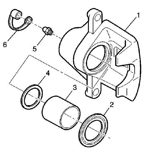
Fig. 8: Exploded View Of Brake Caliper
During brake caliper inspection on the Buick Enclave, also check for torn dust boots, fluid leakage around the piston, seized guide pins, damaged pin boots, uneven pad contact marks, and signs of overheating. A caliper that does not slide or release correctly can quickly damage new pads and rotors, so the cause of abnormal wear should be corrected before the brake system is returned to service.
WARNING: Refer to Brake Dust Warning. Use approved cleaning methods when working around brake pads, rotors, and caliper hardware, and avoid breathing dust from the brake assembly.
2. Inspect the caliper piston dust boot seal (2) for cracks, tears, cuts, deterioration, hardening, swelling, and improper seating in the caliper body. The dust boot protects the piston and bore area from moisture and road debris, so any damage here can lead to corrosion, piston binding, or uneven brake release. If any of these conditions are present, the brake caliper requires overhaul or replacement.
3. Inspect for brake fluid leakage around the caliper piston dust boot seal (2) and on the disc brake pads. Any sign of wetness, staining, or fluid contamination near the piston area should be treated seriously. If there is evidence of brake fluid leakage, the brake caliper requires overhaul or replacement, and any contaminated brake pads should not be reused.
4. Inspect for smooth and complete travel of the caliper pistons into the caliper bores. The piston should move evenly without sticking, tilting, binding, or requiring excessive force.
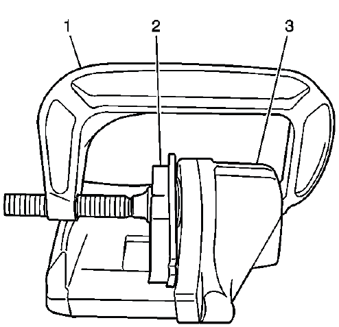
Fig. 9: Compressing Caliper Piston
The movement of the caliper pistons into the caliper bores should be smooth and controlled. If a caliper piston is frozen, difficult to bottom, returns unevenly, or does not move straight into the bore, the caliper requires overhaul or replacement. On the Buick Enclave, a sticking caliper piston can quickly cause uneven pad wear, brake drag, overheating, rotor scoring, and a brake pull during stopping.
- For single piston caliper applications, insert a discarded inner brake pad (2) or a block of wood in front of the piston. Using a large C-clamp (1) installed over the body of the caliper (3) and against the brake pad or block of wood, slowly bottom the piston in the bore. Apply pressure gradually so the piston moves straight and the dust boot is not pinched.
- For dual piston caliper applications, insert a discarded inner brake pad (2) or a block of wood in front of the pistons. Using 2 large C-clamps (1) installed over the body of the caliper (3) and against the brake pad or block of wood, slowly bottom the pistons evenly into the bores. Both pistons should move at a similar rate; if one piston resists movement, the caliper should be inspected further before reuse.
FRONT DISC BRAKE MOUNTING AND HARDWARE INSPECTION
WARNING: Refer to Brake Dust Warning. Clean the brake area safely before inspection and do not use compressed air to blow dust from the caliper, bracket, or pad surfaces.
1. Inspect the fluid level in the brake master cylinder reservoir. This should be done before compressing the caliper pistons because fluid will be pushed back toward the reservoir as the pistons move into the caliper bores.
2. If the brake fluid level is midway between the maximum-full point and the minimum allowable level, no brake fluid needs to be removed from the reservoir before proceeding. Continue to monitor the level during piston compression.
3. If the brake fluid level is higher than midway between the maximum-full point and the minimum allowable level, remove brake fluid to the midway point before proceeding. This helps prevent overflow when the pistons are compressed. Use clean equipment and do not allow dirt or moisture to enter the reservoir.
4. Raise and support the vehicle. Refer Lifting and Jacking the Vehicle. Use the correct lift points and verify that the vehicle is stable before working around the front suspension and brake assemblies.
5. Remove the tire and wheel assembly. Refer to Tire and Wheel Removal and Installation. With the wheel removed, inspect the visible brake hose, caliper, bracket, rotor face, and pad area before disassembly.
6. Grasp the brake caliper housing and try to move the brake caliper housing up/down and forward/reverse in relation to the brake caliper mounting bracket. If excessive looseness is observed, the brake caliper bracket bushings and/or the brake caliper mounting bolts may need to be replaced. Movement should be controlled and smooth, not loose, rattling, or uneven.
7. Compress the front caliper pistons. Work slowly and keep an eye on the master cylinder reservoir level while the pistons move inward.
- Install a large C-clamp over the top of the caliper housing and against the back of the outboard pad.
- Slowly tighten the C-clamp until the pistons are pushed completely into the caliper bores. Do not force the piston if resistance is excessive, because that may indicate a caliper or hose concern.
- Remove the C-clamp from the caliper after the pistons are fully seated.
8. With the pistons compressed into the caliper bores, grasp the brake caliper housing and slide it back and forth on the brake caliper mounting bolts. Check for smooth operation through the full slide range. If the brake caliper housing slide force is high or the brake caliper housing does not slide smoothly, inspect the brake caliper mounting bolts and/or the brake caliper mounting bracket bushings for wear, corrosion, distortion, or damage. If wear or damage conditions are found, replacement of the brake caliper mounting bolts and/or the brake caliper mounting bracket bushings is necessary.
9. Remove the brake caliper mounting bolts from the brake caliper mounting bracket and support the brake caliper using heavy mechanics wire. Do Not remove the hydraulic brake hose from the caliper. Refer to Front Brake Caliper Replacement. Supporting the caliper prevents the brake hose from being stretched, twisted, or used as a hanger for the caliper weight.
10. Remove the disc brake pads from the brake caliper mounting bracket. Note the position of the inner and outer pads, the wear sensor location, and the condition of the contact points before cleaning the bracket.
NOTE: When replacing the disc brake pads, maintain the same disc brake pad wear sensor orientation. Incorrect orientation can cause poor warning function, unwanted noise, or interference with the rotor.
11. Inspect the disc brake pad mounting hardware for the following:
- Missing mounting hardware
- Excessive corrosion
- Bent mounting tabs
- Looseness at the brake caliper mounting bracket
- Looseness at the disc brake pads
- Excessive contaminants in the brake caliper mounting bracket surface and threads.
12. If any of the conditions listed are found, the disc brake pad mounting hardware requires replacement. Reusing damaged or corroded hardware can keep the pads from sliding correctly and may lead to uneven wear, brake drag, clicking noise, or poor pad release.
13. Ensure the disc brake pads are held firmly in place on the brake caliper mounting bracket, yet slide easily on the mounting hardware without binding. The pads should not be loose enough to rattle, but they also should not require force to move in the bracket. On the Buick Enclave, correct pad movement is important for quiet braking and even rotor contact.
14. Inspect the brake caliper guide pin bolt (1), brake caliper (2), caliper bracket (3) and the guide pin seal (4) for the following:
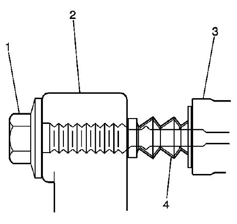
Fig. 10: View Of Caliper, Pin, Boots & Caliper Mounting Bracket
- Binding
- Seizing
- Looseness in the brake caliper mounting bracket
- Bent or damaged brake caliper mounting bolts
- Cracked or torn boots
- Missing boots
- Bent or damaged brake caliper mounting bracket
Any guide pin or boot problem should be corrected before the brakes are reassembled. A seized or dry guide pin can make one pad work harder than the other, while a torn boot allows water and grit to enter the sliding surface. For the Buick Enclave, this type of hardware inspection helps prevent repeat brake noise, uneven pad wear, hot rotors, and vibration after disc brake service.
15. If any of the listed conditions are found, the brake caliper mounting hardware requires replacement. Do not reuse guide pins, bolts, boots, or bracket hardware that shows binding, looseness, corrosion, or physical damage, because worn mounting parts can cause uneven pad wear, brake noise, poor release, and reduced braking consistency.
16. Install the disc brake pads to the brake caliper mounting bracket. Make sure the pads are seated squarely in the bracket and can move smoothly on the mounting hardware without being forced into place.
17. Install the disc brake caliper to the brake caliper mounting bracket. Refer to Front Brake Caliper Replacement. After installation, confirm that the caliper is aligned correctly, the hardware is secure, and the brake hose is not twisted, stretched, or positioned against moving suspension components.
REAR DISC BRAKE MOUNTING AND HARDWARE INSPECTION
WARNING: Refer to Brake Dust Warning. Use approved cleaning methods when working around brake pads, rotors, calipers, and mounting hardware, and avoid breathing dust from the brake assembly.
1. Inspect the fluid level in the brake master cylinder reservoir. This check should be made before compressing the rear caliper piston because brake fluid will be pushed back toward the reservoir as the piston moves into the caliper bore.
2. If the brake fluid level is midway between the maximum-full point and the minimum allowable level, no brake fluid needs to be removed from the reservoir before proceeding. Continue watching the reservoir level during caliper piston compression.
3. If the brake fluid level is higher than midway between the maximum-full point and the minimum allowable level, remove brake fluid to the midway point before proceeding. This helps prevent overflow when the rear caliper piston is compressed. Use only clean equipment and do not allow dirt, moisture, or old contaminated fluid to enter the reservoir.
4. Raise and support the vehicle. Refer Lifting and Jacking the Vehicle. Use the correct lift points and verify that the vehicle is stable before removing the wheel or working around the rear suspension and brake assembly.
WARNING: Do not use a service jack in locations other than those specified to lift this vehicle. Lifting the vehicle with a jack in those other locations could cause the vehicle to slip off the jack and roll; this could cause injury or death.
5. Remove the tire and wheel assembly. Refer to Tire and Wheel Removal and Installation. With the wheel removed, inspect the visible rotor surface, caliper housing, brake hose, bracket area, and pad position before disassembly.
6. Grasp the brake caliper housing and try to move the brake caliper housing up/down and forward/reverse in relation to the brake caliper mounting bracket. If excessive looseness is observed, the brake caliper bracket bushings and/or the brake caliper mounting bolts may need to be replaced. The caliper should slide where designed, but it should not rattle, shift unevenly, or feel loose in the bracket.
7. Compress the rear caliper piston. Work slowly and keep the piston movement controlled. On the Buick Enclave, rear brake hardware condition should be checked carefully because a sticking rear caliper can create uneven pad wear, heat marks on the rotor, or a brake drag condition.
- Install a large C-clamp over the top of the caliper housing and against the back of the outboard pad.
- Slowly tighten the C-clamp until the piston is pushed completely into the caliper bores. Do not force the piston if it becomes difficult to move; excessive resistance may indicate a caliper, hose, or piston seal concern.
- Remove the C-clamp from the caliper after the piston has been fully seated.
8. With the piston compressed into the caliper bore, grasp the brake caliper housing and slide it back and forth on the brake caliper mounting bolts. Check for smooth, even movement through the full slide range. If the brake caliper housing slide force is high or the brake caliper housing does not slide smoothly, inspect the brake caliper mounting bolts and/or the brake caliper mounting bracket bushings for wear, corrosion, distortion, or damage. If wear or damage conditions are found, replacement of the brake caliper mounting bolts and/or the brake caliper mounting bracket bushings is necessary.
9. Remove the brake caliper mounting bolts from the brake caliper mounting bracket and support the brake caliper using heavy mechanics wire. Do not disconnect the hydraulic brake hose from the caliper. Refer to Rear Brake Caliper Replacement. Supporting the caliper prevents the hose from being pulled, kinked, twisted, or used to carry the weight of the caliper.
10. Remove the disc brake pads from the brake caliper mounting bracket. Note the position of the inner and outer pads, the wear pattern, and the condition of the contact points before cleaning or replacing the hardware.
11. Inspect the disc brake pad mounting hardware for the following:
- Missing mounting hardware
- Excessive corrosion
- Bent mounting tabs
- Looseness at the brake caliper mounting bracket
- Looseness at the disc brake pads
- Excessive contaminants in the brake caliper mounting bracket surface and threads.
12. If any of the conditions listed are found, the disc brake pad mounting hardware requires replacement. Damaged or corroded hardware can prevent the pads from sliding correctly, which may lead to brake noise, uneven pad wear, drag, overheating, or poor brake pedal feel.
13. Ensure the disc brake pads are held firmly in place on the brake caliper mounting bracket, yet slide easily on the mounting hardware without binding. The pads should not be loose enough to chatter, but they must move freely enough to release after each brake application. For the Buick Enclave, this balance is important for quiet rear brake operation and even rotor contact.
14. Inspect the caliper bolts (1) for the following:
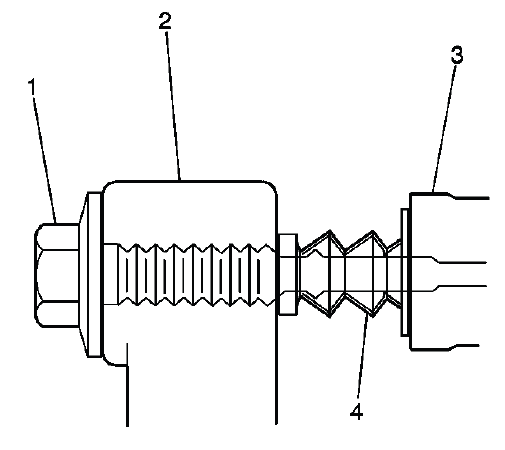
Fig. 11: View Of Caliper, Pin, Boots & Caliper Mounting Bracket
- Binding
- Seizing
- Looseness in the brake caliper mounting bracket (3)
- Bent or damaged brake caliper mounting bolts
- Cracked or torn boots (4)
- Missing boots
- Bent or damaged brake caliper mounting bracket (3)
15. If any of the conditions listed are found, the brake caliper mounting hardware requires replacement. A seized guide pin, torn boot, bent bolt, or damaged bracket can cause the caliper to apply unevenly or fail to release properly after braking.
16. Install the disc brake pads to the brake caliper mounting bracket. Confirm that the pads are positioned correctly, seated against the mounting hardware, and able to slide smoothly without sticking in the bracket.
17. Install the disc brake caliper to the brake caliper mounting bracket. Refer to Rear Brake Caliper Replacement. After the caliper is installed, apply the brake pedal several times before moving the vehicle so the rear pads seat against the rotor and normal pedal height is restored. A final inspection on the Buick Enclave should confirm that the caliper moves properly, the hose is not twisted, the hardware is secure, and no abnormal drag or looseness is present.
