Buick Enclave: Diagnostic Information and Procedures
DIAGNOSTIC CODE INDEX
The diagnostic code index is used as the starting point for Tire Pressure Monitoring System fault isolation. Before replacing any TPMS component, confirm the exact DTC, review the module setup history, verify actual tire pressure with a reliable gauge, and check whether recent tire, wheel, sensor, or RCDLR service has been performed. On the Buick Enclave, several tire pressure monitor faults can be caused by incomplete setup or relearn procedures rather than a failed sensor.
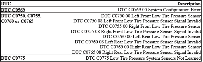
DTC C0569: SYSTEM CONFIGURATION ERROR
Diagnostic Instructions
- Perform the Diagnostic System Check - Vehicle prior to using this diagnostic procedure.
- Review Strategy Based Diagnosis for an overview of the diagnostic approach.
- Diagnostic Procedure Instructions provides an overview of each diagnostic category.
These preliminary steps help confirm that the technician is diagnosing the correct system and not overlooking a related communication, programming, or module setup issue. A configuration fault should always be approached with attention to recent service history, because module replacement or incomplete scan tool setup can set the code even when the tire sensors themselves are not defective.
DTC Descriptor
DTC C0569 00
- System Configuration Error
Circuit/System Description
If the tire type and pressure selection information is not entered with the scan tool during the remote control door lock receiver (RCDLR) setup, the tire pressure monitor indicator icon on the instrument panel cluster (IPC) will flash for 1 minute and then remain illuminated after the ignition switch is cycled ON and the IPC bulb check is complete. If equipped, the driver information center (DIC) will also display a service tire monitor type message. Under these circumstances, DTC C0569 will be set and the tire type and pressure information will need to be entered for the system to function correctly.
In practical service terms, this DTC indicates that the TPMS configuration data has not been completed or accepted by the system. The RCDLR must know the correct tire type and pressure selection so it can interpret sensor data properly and report pressure concerns through the IPC and DIC. For the Buick Enclave, this is especially important after receiver replacement, module programming, or any service event where the tire pressure monitor setup may have been cleared or left unfinished.
Conditions for Running the DTC
The ignition is ON.
When the ignition is switched ON, the system performs its normal checks and verifies whether the required tire pressure monitoring configuration is present. If the needed setup data is missing, the fault can be detected during this operating state.
Conditions for Setting the DTC
The RCDLR has not undergone the programming procedure.
This condition usually points toward an incomplete setup process rather than a direct tire pressure loss. A newly installed or programmed RCDLR must be configured with the correct tire type and pressure selection before the TPMS can operate as intended.
Action Taken When the DTC Sets
- The tire pressure monitor indicator icon on the instrument panel cluster (IPC) flashes for 1 minute and then remains illuminated after the ignition switch is cycled ON and the IPC bulb check is complete.
- If equipped, the driver information center (DIC) displays the suspect tire pressure as dashes.
- If equipped, the DIC displays a service tire monitor type message.
The flashing warning followed by a steady indicator tells the driver that the system is not able to provide normal tire pressure monitoring. Dashes in the pressure display should not be treated as a confirmed low-pressure tire until the configuration problem has been corrected and the sensor readings can be evaluated normally.
Conditions for Clearing the DTC
A current DTC will clear when the RCDLR has undergone the tire type and pressure selection setup procedure and 1 ignition cycle has occurred.
After the scan tool setup is completed, cycle the ignition and recheck for current or history codes. If the setup is accepted and the system recognizes the required tire pressure data, the TPMS indicator behavior should return to normal after the proper cycle.
Diagnostic Aids
A newly replaced RCDLR will set DTC C0569 after programming on its initial ignition ON cycle if the module setup information has not been entered. The Tire Type and Tire Pressure Selection setup must be performed with the scan tool.
If this DTC appears immediately after RCDLR replacement, do not assume that the new receiver is faulty before confirming the setup procedure. Check the service history, scan tool selections, ignition cycle, and any programming confirmation messages. Incomplete module setup is one of the most common reasons this diagnostic code remains active after parts replacement.
Reference Information
Description and Operation
Tire Pressure Monitor Description and Operation
Scan Tool Reference
Control Module References for scan tool information
Use the description and operation information to understand how the tire pressure sensors, RCDLR, IPC, and DIC communicate. The control module reference information should be followed whenever module replacement, setup, programming, or scan tool communication is involved.
Circuit/System Verification
Verify that the DTC C0569 is not set.
- If the DTC is set, perform the RCDLR tire type and pressure selection setup with the scan tool and cycle the ignition. If the DTC resets, replace the RCDLR.
After setup and ignition cycling, verify that the tire pressure monitor indicator no longer flashes and that the pressure values display normally when equipped. If the DTC resets after the correct setup has been performed, the receiver may not be retaining or processing the configuration data correctly.
Repair Instructions
Perform the Diagnostic Repair Verification after completing the diagnostic procedure.
Control Module References for RCDLR replacement, setup and programming
Diagnostic repair verification should confirm both code status and system operation. On the Buick Enclave, this means checking that the warning indicator behavior is normal, the DIC message is no longer present when equipped, and the correct tire pressure information is available after the completed setup.
DTC C0750, C0755, C0760 OR C0765: LOW TIRE PRESSURE SENSOR
Diagnostic Instructions
- Perform the Diagnostic System Check - Vehicle prior to using this diagnostic procedure.
- Review Strategy Based Diagnosis for an overview of the diagnostic approach.
- Diagnostic Procedure Instructions provides an overview of each diagnostic category.
Low tire pressure sensor DTCs should be diagnosed by identifying the affected wheel position, checking actual tire pressure, and confirming sensor communication. A code may be related to a true low-pressure tire, an invalid signal, a weak or damaged sensor, incorrect sensor relearn, or a wheel location mismatch after tire rotation.
DTC Descriptors
DTC C0750 00
- Left Front Low Tire Pressure Sensor
DTC C0750 08
- Left Front Low Tire Pressure Sensor Signal Invalid
DTC C0755 00
- Right Front Low Tire Pressure Sensor
DTC C0755 08
- Right Front Low Tire Pressure Sensor Signal Invalid
DTC C0760 00
- Left Rear Low Tire Pressure Sensor
DTC C0760 08
- Left Rear Low Tire Pressure Sensor Signal Invalid
DTC C0765 00
- Right Rear Low Tire Pressure Sensor
DTC C0765 08
- Right Rear Low Tire Pressure Sensor Signal Invalid
The “00” descriptors generally point toward a low-pressure condition at the named wheel position, while the “08” descriptors indicate that the signal being received is invalid. Before replacing a TPMS sensor, compare the scan tool data with a manual tire pressure reading, inspect the valve stem and sensor area for damage, and confirm that the sensor location matches the wheel position shown by the vehicle. This helps prevent unnecessary replacement when the actual issue is tire pressure loss, an incorrect relearn, or a damaged wheel-mounted sensor after tire service.
For Buick Enclave TPMS diagnosis, always correct tire inflation first, then verify whether the DTC changes, clears, or remains active. If a sensor signal is invalid, inspect for incompatible sensors, sensor battery failure, physical damage, incorrect installation, or interference from recent wheel and tire work. A clean diagnostic process keeps the repair focused and avoids confusing a pressure problem with a communication or sensor identification problem.
Circuit/System Description
The tire pressure monitor (TPM) system has a radio frequency (RF) transmitting pressure sensor in each wheel/tire assembly. As vehicle speed increases, centrifugal force closes the sensor's internal roll switch, which puts the sensor into Rolling mode. The remote control door lock receiver (RCDLR) receives and translates the data contained in the tire pressure sensor RF transmissions into sensor presence, sensor mode and tire pressure.
In normal operation, each wheel sensor sends pressure and status information so the vehicle can determine whether the tire is inflated correctly and whether the sensor is communicating. On the Buick Enclave, the RCDLR acts as the receiver and interpreter for these signals, then provides the information needed for the instrument panel cluster and driver information center messages. If a sensor fails to wake up, has a weak battery, is damaged, or cannot transmit a usable signal, the system may identify the affected wheel position through the corresponding DTC.
Once vehicle speed is greater than 40 km/h (25 mph), the RCDLR waits for the sensors to go into rolling mode.
Rolling mode is important because it confirms that the sensor is active during vehicle movement rather than only being awakened by a service tool. If the receiver does not see the expected sensor activity after the vehicle reaches the required speed, the system begins monitoring for a missing or invalid signal condition.
If one or more sensors do not go into rolling mode or do not transmit at all, the RCDLR will set DTC C0750, C0755, C0760 or C0765 respectively.
Each of these codes is linked to a specific wheel position. Before replacing a sensor, verify that the tire locations have been learned correctly, especially if the tires were recently rotated, replaced, repaired, or serviced. A sensor that appears to be assigned to one corner of the vehicle may actually be installed at another corner if the learn procedure was skipped or completed incorrectly.
Conditions for Running the DTC
Vehicle speed is greater than 40 km/h (25 mph).
The diagnostic runs only when the vehicle is moving fast enough for the wheel sensors to enter rolling mode. This prevents the system from falsely judging a sensor as inactive while the vehicle is parked or moving too slowly for normal rolling-mode transmission.
Conditions for Setting the DTC
- A sensor does not transmit for 18 minutes.
- A sensor low battery condition.
If a sensor remains silent long enough, or if the scan tool reports a low internal sensor battery, the receiver treats that wheel position as unreliable. On a Buick Enclave, this may be caused by a failed sensor, a dead or weak sensor battery, RF interference, an incorrect relearn, a damaged valve stem sensor, or an aftermarket wheel that interferes with sensor operation.
Action Taken When the DTC Sets
- The tire pressure monitor indicator icon on the instrument panel cluster (IPC) flashes for 1 minute and then remains illuminated after the ignition switch is cycled ON and the IPC bulb check is complete.
- If equipped, the driver information center (DIC) displays the suspect tire pressure as dashes.
- If equipped, the DIC displays a service tire monitor type message.
The flashing indicator followed by a steady lamp tells the driver that the TPMS cannot provide normal monitoring for one or more tire positions. When the DIC displays dashes instead of a pressure value, the system is not receiving usable data from that location, so the tire pressure should be checked manually before any assumptions are made about the sensor or the tire.
Conditions for Clearing the DTC
- A current DTC will clear when the malfunction is no longer present and 1 ignition cycle occurs.
- The RCDLR automatically clears the history DTC when a current DTC is not detected in 100 consecutive drive cycles.
After the cause is corrected, the system must see normal sensor operation again before the current fault clears. A history code may remain for a period of time, which is useful when confirming that an intermittent communication concern occurred even if the sensor is working during the current inspection.
Diagnostic Aids
- Some aftermarket wheel valve stem holes are located further from the wheel rim than original equipment wheels. When using the TPM special tool to activate a sensor, ensure the tool antenna is no further than 15 cm (6 in) from the sensor and is aiming upward.
- Aftermarket wheel valve stem locations can cause a sensor to not function correctly.
- A sensor may have been damaged due to a previous wheel/tire service or flat tire event.
- The use of other than GM approved tire sealants can obstruct the sensor pressure sensing port and cause inaccurate tire pressure readings. If this condition is verified, remove the sealer from the tire and replace the sensor. Refer to Tire Pressure Indicator Sensor Replacement (Snap In Style).
- Occasionally sensor transmissions are not received by the RCDLR due to vehicle level RF interference from items such as but not limited to aftermarket ignition systems, DVD players, CB radios or metallic type window tinting.
- The sensor activation procedure may have to be repeated up to 3 times before determining a sensor is malfunctioning. In the event a particular sensor's information is displayed on the special tool upon activation but the horn does not chirp, it may be necessary to rotate the wheel valve stem to a different position due to the RF signal is being blocked by another component.
- Occasionally sensors can become mislocated due to previous tire rotations where the sensor learn procedure was not performed or stray sensor transmissions have been received from other vehicles.
Always learn the sensors to ensure the DTC set is for that actual physical corner of the vehicle. Refer to Tire Pressure Indicator Sensor Learn.
- A sensor low battery condition will set a sensor DTC but will not illuminate the low tire pressure indicator or display a message on the DIC, if equipped. The sensor battery condition can be verified in the scan tool RCDLR data list. If a sensor low battery condition is indicated on the scan tool, the sensor will need to be replaced. Refer to Tire Pressure Indicator Sensor Replacement (Snap In Style).
These diagnostic aids are especially important when the fault appears after tire replacement, wheel repair, tire rotation, or installation of non-original wheels. A TPMS tool reading by itself does not always prove that the vehicle receiver is accepting the sensor signal, so compare tool response, horn confirmation, scan tool data, and the displayed wheel location. For Buick Enclave TPMS diagnosis, repeat the activation procedure when needed and confirm the sensor location before condemning a wheel sensor.
Aftermarket parts and service materials can create symptoms that look like sensor failure. Wheel design may place the sensor deeper or at a different angle, tire sealant can block the sensor pressure port, and RF interference can reduce the receiver's ability to detect transmissions. If the pressure shown on a manual gauge does not match the scan tool or DIC data, inspect the sensor port, valve stem, tire interior, and wheel service history before replacing the RCDLR or multiple sensors.
Reference Information
Description and Operation
Tire Pressure Monitor Description and Operation
Electrical Information Reference
- Circuit Testing
- Connector Repairs
- Testing for Intermittent Conditions and Poor Connections
- Wiring Repairs
Scan Tool Reference
Control Module References for scan tool information
Special Tools
- EL-46079/J-46079 Tire Pressure Monitor Diagnostic Tool
The reference information should be used when confirming sensor operation, module communication, scan tool data, and any related wiring or connector concerns. Although the tire pressure sensors transmit by RF, related module power, ground, communication, and setup issues can still affect how the system reports faults.
Circuit/System Verification
Begin verification by checking actual tire pressure with a known accurate gauge, then compare the readings with scan tool data and any DIC display values. Activate each sensor with the EL-46079/J-46079 tool and confirm that the correct wheel position responds. If a sensor does not respond, responds only intermittently, shows low battery status, or reports from the wrong location, complete the sensor learn procedure and retest before replacing parts.
If the Buick Enclave has recently had tire service, verify that no sensor was damaged during bead breaking, tire removal, flat repair, or sealant use. After all corrections are complete, drive the vehicle above 40 km/h (25 mph) long enough for the sensors to enter rolling mode, then recheck for current DTCs and confirm that the IPC indicator and DIC messages operate normally.
1. Using the EL-46079/J-46079 tool, activate each tire pressure sensor and record each sensor's transmission data and physical location. Verify the EL-46079/J-46079 tool displays the 8-digit ID number, accurate tire pressure within +-27.6 kPa (4 psi), Learn Mode, and at least a 1/4 graph signal strength display.
During this step, treat the special tool data as the baseline for identifying which physical wheel position is actually responding. On the Buick Enclave, this helps separate a weak or missing sensor signal from a sensor location mismatch caused by tire rotation, wheel replacement, or an incomplete relearn procedure. Record the data carefully so the scan tool display can be compared against the true wheel position instead of relying only on the DIC display.
- If any of the parameters listed above are not displayed, replace the suspect tire pressure sensor.
2. With the scan tool, verify tire pressure sensor IDs and locations displayed on the scan tool match the IDs and locations recorded from the special tool.
The ID comparison is important because a sensor may transmit correctly but still be learned to the wrong corner of the vehicle. If the scan tool shows a different ID or location than the special tool record, the issue is likely related to sensor learning or position assignment rather than tire pressure itself.
- If the IDs and locations do not match, perform the Tire Pressure Indicator Sensor Learn.
3. Enable the TPM learn mode. Use the EL-46079/J-46079 tool in simulate mode to learn 4 simulated sensor transmissions into the RCDLR. Verify that all 4 simulated sensor locations, IDs and tire pressures displayed on the TPM special tool match the corresponding scan tool parameters displayed.
This simulated learn procedure checks whether the RCDLR can receive, store, and report sensor data correctly. If the receiver accepts simulated transmissions properly, the fault may be in an individual wheel sensor or in the way the physical sensor signal is reaching the receiver. If the simulated information does not match on the scan tool, the receiver side of the system must be evaluated more closely.
- If the scan tool does not match, replace the RCDLR.
4. Test drive the vehicle above 40 km/h (25 mph) for greater than 2 minutes. With the scan tool, observe the suspect Pressure Sensor Mode data parameter. Verify the sensor mode changes to Rolling.
The road test confirms that the sensor wakes up under real driving conditions and changes from a stationary or learn-related state into Rolling mode. A sensor may respond to the activation tool but still fail to operate correctly once the vehicle is moving. For Buick Enclave TPMS diagnosis, this step is useful when a sensor appears normal in the bay but does not transmit reliably during actual driving.
- If the Pressure Sensor Mode does not change, replace the suspect tire pressure sensor.
Repair Instructions
Perform the Diagnostic Repair Verification after completing the diagnostic procedure.
After repairs are completed, confirm that the pressure readings are displayed correctly, the wheel locations match the learned positions, and no current TPMS DTC returns after an ignition cycle and road test. This verification prevents the vehicle from leaving with a sensor that works only during tool activation but fails during normal operation.
- Tire Pressure Indicator Sensor Replacement (Snap In Style)
- Tire Pressure Indicator Sensor Learn
- Control Module References for RCDLR replacement, programming and setup
DTC C0775: LOW TIRE PRESSURE SYSTEM SENSORS NOT LEARNED
Diagnostic Instructions
- Perform the Diagnostic System Check - Vehicle prior to using this diagnostic procedure.
- Review Strategy Based Diagnosis for an overview of the diagnostic approach.
- Diagnostic Procedure Instructions provides an overview of each diagnostic category.
These diagnostic instructions should be followed before starting direct component replacement. DTC C0775 is commonly related to system learning or receiver setup, so confirming scan tool communication, module history, and recent tire or wheel service can prevent unnecessary sensor replacement.
DTC Descriptor
DTC C0775
- Low Tire Pressure System Sensors Not Learned
Circuit/System Description
If the tire pressure sensor learn procedure has not been performed, the tire pressure monitor indicator icon on the instrument panel cluster (IPC) will flash for 1 minute and then remain illuminated after the ignition switch is cycled ON and the IPC bulb check is complete. If equipped, the driver information center (DIC) will also display a service tire monitor type message. Under these circumstances, DTC C0775 will be set and the tire pressure sensor learn procedure will need to be performed for the system to function correctly.
In normal operation, the RCDLR must know which tire pressure sensor belongs to each wheel position. Without the learn procedure, the system cannot reliably assign the sensor IDs to the correct corners of the vehicle, even if the sensors themselves are transmitting. On the Buick Enclave, this code may appear after RCDLR replacement, tire rotation, wheel sensor replacement, module programming, or any service where the learned sensor positions were cleared or not completed.
Conditions for Running the DTC
The ignition is ON.
When the ignition is switched ON, the module checks whether the required tire pressure sensor learn data is stored. If the learn information is missing, the system identifies the TPMS as incomplete and prepares to set the diagnostic code.
Conditions for Setting the DTC
The remote control door lock receiver (RCDLR) has not undergone the tire pressure sensor learn procedure.
This condition indicates that the receiver does not have a complete learned sensor set. The problem may not be a low tire, a failed sensor, or a wiring issue; it may simply be that the receiver has not been taught the correct sensor IDs and positions.
Action Taken When the DTC Sets
- The tire pressure monitor indicator icon on the instrument panel cluster (IPC) will flash for 1 minute and then remain illuminated after the ignition switch is cycled ON and the IPC bulb check is complete.
- If equipped, the driver information center (DIC) displays a service tire monitor type warning message.
The flashing warning followed by a steady indicator tells the driver that the TPMS is not fully operational. When this code is present, the pressure display may not be reliable until the sensors are learned and the receiver can match each ID to the correct wheel location.
Conditions for Clearing the DTC
A current DTC will clear when the RCDLR has undergone the tire pressure sensor learn procedure and 1 ignition cycle has occurred.
After completing the learn procedure, cycle the ignition and recheck for the DTC. If the system accepts all four sensor IDs and the receiver stores the positions correctly, the code should clear after the required ignition cycle.
Diagnostic Aids
A newly replaced RCDLR will set DTC C0775 on its initial ignition ON cycle. The tire pressure sensor learn procedure must be performed.
This is a key diagnostic point. If DTC C0775 appears immediately after RCDLR replacement or setup, do not assume that the new receiver has failed before completing the tire pressure sensor learn. A receiver without learned sensors cannot report the system normally, even when all four wheel sensors are functional.
Reference Information
Description and Operation
Tire Pressure Monitor Description and Operation
Electrical Information Reference
- Circuit Testing
- Connector Repairs
- Testing for Intermittent Conditions and Poor Connections
- Wiring Repairs
Scan Tool Reference
Control Module References for scan tool information
Use the tire pressure monitor description to understand how the sensors, RCDLR, IPC, and DIC interact. Use the electrical and control module references when scan tool communication, receiver programming, setup, or stored module data must be verified. For Buick Enclave TPMS service, these references are especially useful when a relearn does not complete or when the receiver does not retain learned sensor information.
Circuit/System Verification
Verify that the DTC C0775 is not set.
- If the DTC is set, perform the tire pressure sensor learn procedure. Cycle the ignition. If the DTC resets, replace the RCDLR.
After completing the learn procedure, verify all four sensor IDs, tire pressure values, and wheel locations with the scan tool. If the code resets after a correct relearn and ignition cycle, the RCDLR may not be storing or processing the learned sensor data properly. Confirm the repair by checking that the TPMS indicator no longer flashes, the DIC message is gone when equipped, and the learned wheel positions remain correct after the vehicle is driven.
Repair Instructions
Complete the required repair verification after the learn or receiver service is finished. The final check should include sensor activation, scan tool confirmation, ignition cycling, and a road test when needed so the system can prove that the learned data remains valid during normal vehicle operation.
Perform the Diagnostic Repair Verification after completing the diagnostic procedure. This final verification should confirm that the tire pressure monitor warning behavior is normal, the learned sensor information is retained, and the system does not reset the same DTC after an ignition cycle or a short road test.
- Tire Pressure Indicator Sensor Learn
- Control Module References for RCDLR replacement, setup and programming
SYMPTOMS - TIRE PRESSURE MONITORING
1. Perform the Diagnostic System Check - Vehicle, before using the Symptom Tables in order to verify that all of the following are true:
- There are no DTCs set.
- The control modules can communicate via the serial data link.
The symptom tables should be used only after the basic system check confirms that the modules are communicating and no active diagnostic trouble codes are directing the repair path. On the Buick Enclave, a tire pressure warning may be caused by an actual low tire, an incomplete sensor learn, a receiver issue, RF interference, or a sensor that has been damaged during tire service, so the first step is to separate a system fault from a basic tire condition.
2. Review the system operation in order to familiarize yourself with the system functions. Refer to Tire Pressure Monitor Description and Operation.
Understanding how the RCDLR receives sensor transmissions, stores sensor IDs, and sends messages to the IPC and DIC makes the diagnosis more accurate. A technician should know when the system is reporting a true low-pressure condition and when the warning behavior points toward a communication or sensor identification problem.
Visual/Physical Inspection
- Inspect for aftermarket devices which could affect the operation of the Tire Pressure Monitoring (TPM) System. Refer to Checking Aftermarket Accessories.
- Inspect the easily accessible or visible system components for obvious damage or conditions which could cause the symptom.
The visual inspection should include the tires, valve stems, wheel condition, sensor mounting areas, recent tire repairs, aftermarket wheels, window tint, added electronics, and any evidence of tire sealant. A simple inspection can often reveal the cause before scan tool testing becomes necessary, especially after tire rotation, wheel replacement, or flat tire repair.
Intermittent
Faulty electrical connections or wiring may be the cause of intermittent conditions. Refer to Testing for Intermittent Conditions and Poor Connections.
Intermittent TPMS concerns may also be related to weak RF signal reception, sensor battery condition, poor module communication, or a sensor that responds only when the wheel is positioned a certain way. If the concern is not present during inspection, review the customer’s description carefully, including driving speed, outside temperature, recent tire work, and whether the indicator flashes or stays steadily illuminated.
Symptom List
Refer to Low Tire Pressure Indicator Malfunction in order to diagnose the symptom.
Use the low tire pressure indicator malfunction path when the warning lamp behavior does not match the actual tire condition or when the system appears to report pressure incorrectly. Always confirm tire pressure manually before relying on displayed values alone.
LOW TIRE PRESSURE INDICATOR MALFUNCTION
Diagnostic Instructions
- Perform the Diagnostic System Check - Vehicle prior to using this diagnostic procedure.
- Review Strategy Based Diagnosis for an overview of the diagnostic approach.
- Diagnostic Procedure Instructions provides an overview of each diagnostic category.
These diagnostic instructions help keep the repair process organized. Rather than replacing a tire pressure sensor immediately, confirm the warning pattern, verify module communication, compare manual pressure readings, and check whether the sensors have been learned correctly.
Circuit/System Description
The remote control door lock receiver (RCDLR) receives a radio frequency (RF) transmission from each tire pressure sensor. Each sensor has its own unique identification (ID) code, which it transmits as part of each RF message, that must be learned into the RCDLR memory. Once all 4 IDs have been learned and vehicle speed is greater than 40 km/h (25 mph), the RCDLR continuously compares IDs in received transmission to its learned IDs to determine if all 4 sensors are present. If the RCDLR detects a low tire pressure condition or a malfunction in the system, it will send a serial data message to the instrument panel cluster (IPC) requesting the appropriate tire pressure monitor indicator illumination and also to display the appropriate data message on the driver information center (DIC), if equipped.
In normal operation, the system depends on three things working together: each wheel sensor must transmit accurately, the RCDLR must recognize the learned ID, and the IPC or DIC must display the correct warning information. If one of those steps fails, the driver may see a flashing lamp, a steady low-pressure indicator, dashes instead of pressure values, or a service tire monitor message. For Buick Enclave TPMS diagnosis, the warning pattern is an important clue because it helps separate low inflation from a system communication or sensor-learn problem.
Diagnostic Aids
- If unsure about the condition, cycle the ignition and observe the tire pressure monitor indicator icon. If the tire pressure monitor indicator icon is continuously illuminated after the IPC bulb check is completed, a low tire pressure condition is present. Check the tires for damage or leaks and inflate to the tire placard specifications. Refer to Vehicle Certification, Tire Placard, Anti-Theft and Service Parts ID Label.
If the tire pressure monitor indicator icon flashes for 1 minute after the IPC bulb check is completed and then remains illuminated, a tire pressure monitor system DTC is set. Perform the Diagnostic System Check - Vehicle to proceed with the proper diagnosis.
- Temperature can greatly effect tire pressures. Low tire pressure on a cold morning may cause the tire pressure monitor indicator icon to turn ON. The air pressure in the tire increases as the ambient temperature rises or as the tire warms up while the vehicle is driven. The pressure may increase enough to exceed the predetermined low pressure threshold which will turn OFF the tire pressure monitor indicator icon.
- Some aftermarket wheel valve stem holes are located further from the wheel rim than original equipment wheels. When using the TPM special tool to activate a sensor, ensure the tool antenna is no further than 15 cm (6 in) from the sensor and is aiming upward.
- Aftermarket wheel value stem locations can cause a sensor to not function correctly.
- A sensor may have been damaged due to a previous wheel/tire service or flat tire event.
- The use of other than GM approved tire sealants can obstruct the sensor pressure sensing port and cause inaccurate tire pressure readings. If this condition is verified, remove the sealer from the tire and replace the sensor. Refer to Tire Pressure Indicator Sensor Replacement (Snap In Style).
- Occasionally sensor transmissions are not received by the RCDLR due to vehicle level RF interference from items such as but not limited to aftermarket ignition systems, DVD players, CB radios or metallic type window tinting.
- The sensor activation procedure may have to be repeated up to 3 times before determining a sensor is malfunctioning. In the event a particular sensor's information is displayed on the special tool upon activation but the horn does not chirp, it may be necessary to rotate the wheel valve stem to a different position due to the RF signal is being blocked by another component.
- Occasionally sensors can become mislocated due to previous tire rotations where the sensor learn procedure was not performed or stray sensor transmissions have been received from other vehicles.
If the lamp stays on steadily after the bulb check, begin with tire pressure and tire condition, not sensor replacement. Inspect each tire for punctures, sidewall damage, bead leaks, valve stem leaks, and pressure below the placard value. If the lamp flashes for approximately 1 minute and then stays on, treat the condition as a system fault and continue with scan tool diagnosis.
Temperature-related pressure changes are common and should be explained during diagnosis. A tire that is close to the low-pressure threshold may trigger the indicator on a cold morning, then appear normal later after the air warms and expands. This does not mean the system is defective; it means the cold tire pressure should be adjusted to the placard specification so the Buick Enclave does not operate near the warning threshold.
Aftermarket wheels can create TPMS issues even when the sensors are functional. Different valve stem angles, deeper sensor placement, or wheel material can weaken the activation signal or prevent the receiver from hearing the sensor consistently. When using the TPM tool, keep the antenna close to the sensor location and repeat activation when needed before deciding that a sensor has failed.
Previous tire service is another common source of TPMS concerns. A sensor can be cracked by tire machine contact, damaged during bead breaking, contaminated by sealant, or left installed in a wheel that was moved to a different position without completing the learn procedure. If tire sealant has been used, inspect the sensor pressure port carefully because a blocked port can cause pressure readings that do not match the actual tire pressure.
RF interference should be considered when the sensor responds inconsistently or when several sensors appear to fail at once. Added electronics, aftermarket ignition systems, CB radios, DVD equipment, metallic window film, and nearby stray transmissions can affect signal reception. For Buick Enclave service, compare special tool results with scan tool data and learned wheel positions before replacing the RCDLR or multiple sensors.
When sensor location is uncertain, perform the tire pressure sensor learn procedure and confirm that each physical wheel position matches the displayed location. A mislearned sensor can make the vehicle appear to report the wrong tire, which may lead to incorrect diagnosis if the technician only follows the DIC location without verifying the actual sensor ID.
Always learn the sensors to ensure the DTC set is for that actual physical corner of the vehicle. Refer to Tire Pressure Indicator Sensor Learn. This step is important after tire rotation, wheel replacement, sensor service, or any situation where a sensor may have been learned to the wrong position. On the Buick Enclave, confirming the learned sensor location prevents a technician from diagnosing the wrong tire or replacing a sensor that is actually installed at a different corner.
Reference Information
Description and Operation
Tire Pressure Monitor Description and Operation
Electrical Information Reference
- Circuit Testing
- Connector Repairs
- Testing for Intermittent Conditions and Poor Connections
- Wiring Repairs
Scan Tool Reference
Control Module References for scan tool information
Special Tools
- J 46079 Tire Pressure Monitor Diagnostic Tool
The reference information should be used to confirm how the tire pressure monitor sensors, RCDLR, IPC, and scan tool data work together. Even though the wheel sensors communicate by radio frequency, the diagnostic path may still involve module setup, serial data communication, connector integrity, and intermittent electrical conditions. The J 46079 tool is used to activate and simulate sensor transmissions so the technician can compare physical tire readings, learned sensor IDs, and module response.
Circuit/System Verification
NOTE: Low tire pressure in one or more tires is indicated by a continuously illuminated tire pressure monitor indicator icon after the IPC bulb check is completed. If equipped with a DIC, a check tire pressure type message will also be displayed.
It is not necessary to perform the Learn procedure for a low tire condition.
When a TPM DTC is set, the tire pressure monitor indicator icon will flash for 1 minute after the IPC bulb check is completed and then remains illuminated. If equipped with a DIC, a service tire monitor type message will also be displayed.
Before beginning component replacement, separate a true low-pressure tire condition from a TPMS system fault. A steady indicator after the bulb check usually points toward actual low tire pressure, while a flashing indicator followed by a steady lamp points toward a stored tire pressure monitoring DTC. This distinction matters because a low tire does not require a sensor learn procedure, but a TPMS fault may require sensor activation, scan tool verification, module setup, or receiver testing.
1. Verify all tires are inflated to the proper pressure +- 10%. Refer to Vehicle Certification, Tire Placard, Anti-Theft and Service Parts ID Label. Check the tires cold when possible, and use the placard value rather than the pressure molded into the tire sidewall.
- If not within the specified range, adjust all tire pressures to specification and drive the vehicle over 40 km/h (25 mph) for greater than 2 minutes. Verify the tire pressure monitor indicator icon is OFF.
If the indicator turns off after the pressure is corrected and the vehicle is driven, the concern was most likely caused by an actual inflation issue rather than a failed sensor. On the Buick Enclave, seasonal temperature drops, slow bead leaks, punctures, and valve stem leaks can all trigger a low-pressure warning without indicating a TPMS hardware fault.
2. Using the J 46079 tire pressure monitor diagnostic tool, activate each B2 Tire Pressure Sensor and record each sensor tire pressure reading. Check the tire pressures with a known accurate hand held tire pressure gauge. Verify that the pressure readings from the special tool do not differ more than 27.6 kPa (4 psi) from the actual tire pressure readings.
- If not within the specified range, replace the appropriate B2 Tire Pressure Sensor.
This comparison confirms whether the sensor pressure value is believable. A sensor that transmits an ID but reports pressure outside the allowed difference may have a blocked pressure port, internal sensor fault, sealant contamination, or damage from previous tire service. Always compare tool data with a reliable manual gauge before deciding that the sensor reading is incorrect.
3. Using a scan tool, enable the TPM learn mode. Use the J 46079 tire pressure monitor diagnostic tool in simulate mode to learn 4 simulated sensor transmissions into the RCDLR. Observe tire pressures in the scan tool data display. Verify the simulated tire pressures do not differ more than +/-27.6 kPa (4 psi) of the scan tool reading.
- If not within the specified range, replace the RCDLR.
The simulated sensor test checks the receiver and scan tool data path without depending on the actual wheel sensors. If the RCDLR cannot learn or report simulated transmissions accurately, the fault is likely on the receiver/module side rather than at an individual tire sensor. This prevents unnecessary replacement of all four sensors when the module is not processing sensor information correctly.
4. Using a scan tool, perform the instrument panel special functions Lamp Test. Command the instrument panel warning lamps ON and OFF. Verify the tire pressure monitor indicator icon turns ON and OFF.
- If the tire pressure monitor icon does not turn ON and OFF, replace the IPC.
This test confirms that the warning indicator itself can be controlled by the instrument panel cluster. If the TPMS system data is correct but the lamp does not respond during the commanded test, the problem may be in the IPC rather than the tire pressure sensors or RCDLR. A proper lamp test helps avoid chasing sensor faults when the warning display cannot operate as commanded.
5. Ignition ON, use the scan tool to setup the Tire Type/Pressure Selection in the RCDLR Module Setup menu. Refer to the Vehicle Certification, Tire Placard, Anti-Theft and Service Parts ID Label. Drive the vehicle over 40 km/h (25 mph) for greater than 2 minutes. Verify the tire pressure monitor indicator icon is OFF.
- If the tire pressure monitor indicator icon is ON, replace the RCDLR.
The tire type and pressure selection must match the vehicle placard information so the RCDLR can apply the correct pressure thresholds. If this setup is incomplete or incorrect, the system may continue to display a warning even when the tires and sensors are functioning. For Buick Enclave TPMS repair, always verify module setup after receiver replacement, programming, or configuration-related DTCs.
Repair Instructions
Perform the Diagnostic Repair Verification after completing the diagnostic procedure. The final verification should include confirming correct tire pressures, proper sensor response, accurate scan tool data, correct IPC indicator operation, and no returning TPMS DTCs after an ignition cycle and road test.
- Tire Pressure Indicator Sensor Replacement (Snap In Style)
- Tire Pressure Indicator Sensor Learn
- Control Module References for IPC or RCDLR replacement, setup and programming
After any sensor, IPC, or RCDLR repair, verify that the tire pressure monitor indicator behaves normally during bulb check and that the DIC message, if equipped, matches the actual system condition. A complete repair should leave the Buick Enclave with all sensor locations learned, all displayed pressures reasonable, and the tire pressure monitoring warning off during normal driving.
