Buick Enclave: Crankshaft & Main Bearings
* PLEASE READ THIS FIRST *
NOTE: Examples used in this article are general in nature and do not necessarily relate to a specific engine or system. Illustrations and procedures have been chosen to guide mechanic through engine overhaul process. Descriptions of processes of cleaning, inspection, assembly and machine shop practice are included.
Always refer to appropriate engine overhaul article, if available, in the ENGINES section for complete overhaul procedures and specifications for the vehicle being repaired. Crankshaft and main bearing service requires exact measurements, clean handling, correct cap orientation, and the proper bearing selection for the engine being repaired. When this information is used for a Buick Enclave engine overhaul, treat it as general guidance and confirm all limits, torque values, seal details, and bearing clearances in the specific engine service procedure.
REMOVAL
NOTE: Examples used in this article are general in nature and do not necessarily relate to a specific engine or system. Illustrations and procedures have been chosen to guide mechanic through engine overhaul process. Descriptions of processes of cleaning, inspection, assembly and machine shop practice are included.
Always refer to appropriate engine overhaul article, if available, in the ENGINES section for complete overhaul procedures and specifications for the vehicle being repaired.
Ensure all main bearing caps are marked for location on cylinder block. Some main bearing caps have an arrow stamped on them. The arrow must face timing belt or timing chain end of engine. Remove main bearing cap bolts. Remove main bearing caps. Carefully remove crankshaft. Use care not to bind crankshaft in cylinder block during removal. Main bearing caps are machined in position with the block and must not be mixed, reversed, or installed in the wrong location. If the caps are not already clearly marked, mark them before removal in a way that will not damage the machined surfaces.
Lift the crankshaft evenly and avoid dragging the journals across the bearing saddles or block edges. The crankshaft is heavy and can be damaged by a small nick on a journal or seal surface. If resistance is felt during removal, stop and check that all caps, thrust components, fasteners, seals, and related parts have been fully released before applying more force.
CLEANING & INSPECTION
NOTE: Examples used in this article are general in nature and do not necessarily relate to a specific engine or system. Illustrations and procedures have been chosen to guide mechanic through engine overhaul process. Descriptions of processes of cleaning, inspection, assembly and machine shop practice are included.
Always refer to appropriate engine overhaul article, if available, in the ENGINES section for complete overhaul procedures and specifications for the vehicle being repaired.
Thoroughly clean crankshaft using solvent. Dry with compressed air. Ensure all oil passages are clear and free of sludge, rust, dirt and metal chips. Oil passages must be cleaned with extra care because hidden debris can travel directly to the bearings after start-up. Use suitable brushes and compressed air until every passage is open and dry, then protect the crankshaft from dust while measurements are being prepared.
Inspect crankshaft for scoring and nicks. Inspect crankshaft for cracks using Magnaflux procedure. Inspect rear seal area for grooving or damage. Inspect bolt hole threads for damage. If pilot bearing or bushing is used, check pilot bearing or bushing fit in crankshaft. Inspect crankshaft gear for damaged or cracked teeth. Replace gear if damaged. Ensure oil passage plugs are tight (if equipped).
Minor scratches on a journal may look harmless, but any roughness can wipe oil from the bearing surface and lead to premature bearing wear. Run a fingernail gently across suspect areas; if the mark can be felt, the crankshaft may require polishing, grinding, or replacement depending on the specification. The rear main seal surface should also be smooth, because a groove in this area can cause an oil leak even with a new seal.
Using micrometer, measure all journals in 4 areas to determine journal taper, out-of-round and undersize. See Fig. 20. Some crankshafts can be reground to the next largest undersize, depending on the amount of wear or damage. Crankshafts with rolled fillet cannot be reground and must be replaced.
Journal measurement should be done with a clean, calibrated micrometer and recorded for each main and connecting rod journal. Measuring in several locations shows whether the journal is worn evenly or has taper and out-of-round conditions that would affect oil clearance. On a Buick Enclave engine rebuild, these measurements determine whether standard bearings can be used, undersize bearings are required, or the crankshaft is no longer serviceable.
Pay close attention to the fillet areas at the edges of each journal. These curved transitions add strength to the crankshaft, and improper grinding can weaken them. If the crankshaft design uses rolled fillets, follow the service recommendation exactly rather than treating it like a conventional regrindable crankshaft.
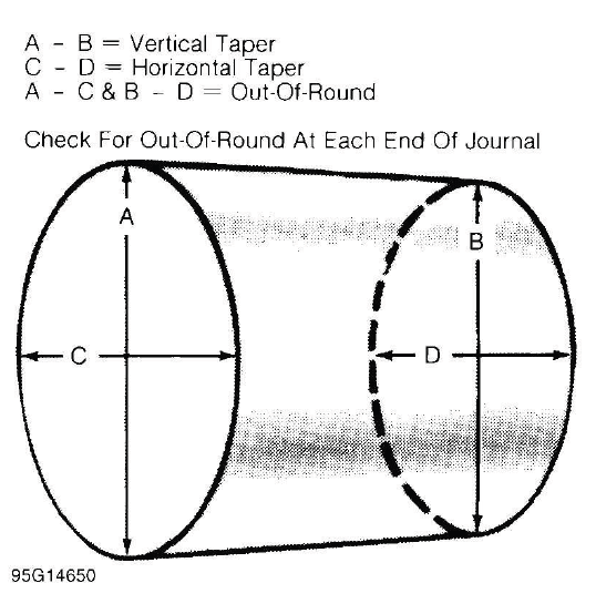
Fig. 20: Measuring Crankshaft Journals
Crankshaft journal runout should be checked. Install crankshaft in "V" blocks or bench center. Position dial indicator with tip resting on the main bearing journal area. See Fig. 21. Rotate crankshaft and note reading. The crankshaft must sit securely on clean supports so the indicator reading reflects the crankshaft condition, not movement of the setup.
Journal runout must not exceed specification. Repeat procedure on all main bearing journals. Crankshaft must be replaced if runout exceeds specification. Excessive runout can cause vibration, uneven bearing loading, oil clearance changes, and accelerated wear after the engine is assembled. A crankshaft that fails this test should not be corrected by bearing selection alone.
While checking runout, rotate the crankshaft slowly and watch the dial indicator for a smooth pattern. Sudden jumps may indicate dirt on the support surface, a damaged journal, or an unstable setup. Recheck the reading if anything appears inconsistent before making a final repair decision.
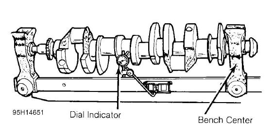
Fig. 21: Measuring Crankshaft Main Bearing Journal Runout
INSTALLATION
NOTE: Examples used in this article are general in nature and do not necessarily relate to a specific engine or system. Illustrations and procedures have been chosen to guide mechanic through engine overhaul process. Descriptions of processes of cleaning, inspection, assembly and machine shop practice are included.
Always refer to appropriate engine overhaul article, if available, in the ENGINES section for complete overhaul procedures and specifications for the vehicle being repaired. Bearing shell location, thrust bearing position, rear seal installation, lubricant choice, and cap torque sequence must follow the correct engine-specific instructions.
Install upper main bearing in cylinder block. Ensure lock tab is properly located in cylinder block. Install bearings in main bearing caps. Ensure all oil passages are aligned. Install rear seal (if removed). Bearing shells must be installed into clean, dry saddles so they seat fully against the block and cap. Do not place oil behind the bearing shell unless the engine procedure specifically instructs it, because trapped oil or debris can change bearing crush and clearance.
Before the crankshaft is set into the block, apply the recommended assembly lubricant or clean engine oil to the bearing surfaces that contact the journals. Keep the bearing backs, cap mating surfaces, and block saddles clean. A small particle under a main bearing can distort the shell enough to reduce clearance and damage the crankshaft shortly after start-up.
Lower the crankshaft gently into position and make sure it sits evenly on the upper bearings. Install the main bearing caps in their original locations and directions, then tighten the fasteners in the specified stages and sequence. For Buick Enclave crankshaft installation, check that the crankshaft rotates smoothly as the caps are tightened, rather than waiting until all fasteners are fully torqued.
After the caps are tightened, verify main bearing clearance, crankshaft end play, and rear seal placement before continuing with the rest of the engine assembly. Any binding, tight spot, or unusual resistance should be investigated immediately. Correcting a clearance or cap alignment issue at this stage is far easier than diagnosing bearing noise, low oil pressure, or oil leakage after the engine is installed and running.
Ensure crankshaft journals are clean. Lubricate upper main bearings with clean engine oil. Carefully install crankshaft. Check each main bearing clearance using Plastigage method. See MAIN & CONNECTING ROD BEARING CLEARANCE. The journals must be completely free of dirt, lint, solvent residue, metal particles, and old oil film before the crankshaft is lowered into place. Even a very small particle between the journal and bearing surface can change oil clearance and damage the bearing during the first minutes of operation.
Set the crankshaft into the block gently and keep it level while lowering it onto the upper main bearings. Do not drag the journals across the bearing edges or allow the crankshaft to bind in the saddles. During Buick Enclave engine assembly, this step should feel controlled and smooth; if the crankshaft does not sit naturally in the bearings, stop and inspect the bearing shells, thrust surfaces, cap locations, and block saddles before continuing.
Once clearance is checked, lubricate lower main bearing and journals. Install main bearing caps in original location. Install rear seal in rear main bearing cap (if removed). Some rear main bearing caps require sealant to be applied in corners to prevent oil leakage. The lower bearing shells must be seated fully in the caps, with the locating tabs positioned correctly and the oil holes or grooves aligned as required. Apply sealant only where specified, because excess sealant can squeeze into unwanted areas and contaminate the oil system.
Install and tighten all bolts except thrust bearing cap to specification. Tighten thrust bearing cap bolts finger tight only. Some models require that thrust bearing be aligned. On most applications, crankshaft must be moved rearward then forward. Procedure may vary with manufacturer. Thrust bearing cap is then tightened to specification. Ensure crankshaft rotates freely. Crankshaft end play should be checked. See CRANKSHAFT END PLAY.
Aligning the thrust bearing is important because it controls the forward and rearward movement of the crankshaft. If the thrust surfaces are not seated squarely, the crankshaft may bind, the end play may be incorrect, or the thrust bearing may wear quickly. After the cap is tightened, rotate the crankshaft by hand and feel for any tight spot before moving on to piston and connecting rod installation.
CRANKSHAFT END PLAY
NOTE: Examples used in this article are general in nature and do not necessarily relate to a specific engine or system. Illustrations and procedures have been chosen to guide mechanic through engine overhaul process. Descriptions of processes of cleaning, inspection, assembly and machine shop practice are included.
Always refer to appropriate engine overhaul article, if available, in the ENGINES section for complete overhaul procedures and specifications for the vehicle being repaired. Crankshaft end play limits are engine-specific and must be checked against the correct service specification before the engine is assembled further.
Dial Indicator Method
Crankshaft end play can be checked using dial indicator. Mount dial indicator on rear of cylinder block. The indicator base must be secure, and the gauge should be positioned so the movement being measured is straight in line with crankshaft travel. A loose mount or angled indicator tip can give an inaccurate reading.
Position dial indicator tip against rear of crankshaft. Ensure tip is resting against flat surface. The contact point should be clean and smooth so the indicator needle moves steadily as the crankshaft is shifted.
Pry crankshaft rearward. Adjust dial indicator to zero. Pry crankshaft forward and note reading. Crankshaft end play must be within specification. If end play is not within specification, check for faulty thrust bearing installation or worn crankshaft. Some applications offer oversize thrust bearings. Move the crankshaft gently and avoid prying against machined sealing surfaces or bearing areas. The goal is to move the crankshaft fully in both directions without damaging the block, cap, or crankshaft.
If end play is too tight, the crankshaft may bind as the engine warms or when load is applied through the drivetrain. If end play is excessive, the crankshaft can move forward and rearward too much, causing noise, thrust bearing wear, seal wear, or damage to related components. On a Buick Enclave engine rebuild, this measurement should be verified before the rotating assembly is considered ready for final assembly.
Feeler Gauge Method
Crankshaft end play can be checked using feeler gauge. Pry crankshaft rearward. Pry crankshaft forward. Using feeler gauge, measure clearance between crankshaft and thrust bearing surface. See Fig. 22. Use a clean feeler gauge and insert it carefully between the thrust surface and the crankshaft. The gauge should slide with light resistance and should not be forced into the gap.
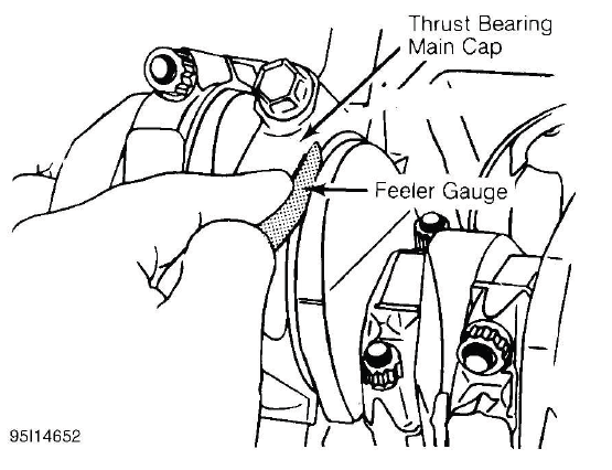
Fig. 22: Checking Crankshaft End Play
Crankshaft end play must be within specification. If end play is not within specification, check for faulty thrust bearing installation or worn crankshaft. Some applications offer oversize thrust bearings. Recheck the thrust bearing position, cap installation, bearing shell seating, and crankshaft thrust surface condition before replacing parts. A measurement outside the limit usually points to an assembly issue, worn thrust faces, incorrect bearing selection, or crankshaft damage.
CYLINDER BLOCK
NOTE: Examples used in this article are general in nature and do not necessarily relate to a specific engine or system. Illustrations and procedures have been chosen to guide mechanic through engine overhaul process. Descriptions of processes of cleaning, inspection, assembly and machine shop practice are included.
Always refer to appropriate engine overhaul article, if available, in the ENGINES section for complete overhaul procedures and specifications for the vehicle being repaired. Block material, bore design, thread repair limits, deck height, and machining options can vary, so every inspection result should be compared with the correct engine information.
Block Cleaning
Only cast cylinder blocks should be hot tank cleaned. Aluminum cylinder blocks should be cleaned using cold tank method. Cylinder block is cleaned in order to remove carbon deposits, gasket residue and water jacket scale. Remove oil gallery plugs, freeze plugs and cam bearings before cleaning block. Cleaning the block is not only about appearance; it removes abrasive material, coolant scale, sludge, and old gasket debris that can damage the rebuilt engine after start-up.
Oil galleries and coolant passages require special attention. Deposits hidden inside the block can break loose later and restrict oil flow, contaminate bearings, or reduce cooling efficiency. After cleaning, the block should be rinsed, dried with compressed air, and protected from flash rust if the material is prone to corrosion. For a Buick Enclave engine overhaul, a clean block gives more accurate measurements and lowers the risk of early bearing or cooling system problems.
Block Inspection
Visually inspect the block. Check suspected areas for cracks using the Dye Penetrant inspection method. Block may be checked for cracks using the Magnaflux method. Start with a careful visual inspection under good lighting, then use the correct crack-detection method for the block material. Some cracks are difficult to see until the surface is cleaned and the suspected area is tested properly.
Cracks are most commonly found at the bottom of cylinders, main bearing saddles, near expansion plugs and between cylinders and water jackets. Inspect lifter bores for damage. Inspect all head bolt holes for damaged threads. Threads should be cleaned using tap to ensure proper head bolt torque. Consult machine shop concerning possible welding and machining (if required).
Head bolt holes must be clean and undamaged because incorrect thread condition can change clamping force and lead to head gasket sealing problems. Main bearing saddles should be inspected for fretting, scoring, cap movement, or distortion. If the block shows signs of overheating, coolant contamination, bearing failure, or previous repair, it should be evaluated by a qualified machine shop before parts are ordered.
Thread cleaning should restore the original thread path without removing unnecessary material. Use the correct tool and keep debris out of oil and coolant passages. If any threads are pulled, cracked, or badly worn, repair inserts or machining may be required before the block can be reused safely.
Cylinder Bore Inspection
Cylinder bore inspection should be performed only after the block has been cleaned and the ridge, glaze, and heavy deposits have been removed. Check each bore for scoring, taper, out-of-round, corrosion, cracks, and wear at the top ring travel area. The condition of the cylinder bore determines whether the block can be honed, must be bored oversize, or should be replaced.
Measure each cylinder in more than one direction and at several heights. Wear is often greatest near the top of ring travel, while out-of-round can appear from heat, load, or block distortion. Accurate bore measurements are essential before selecting pistons and rings. During Buick Enclave engine service, cylinder bore condition directly affects compression, oil consumption, piston noise, ring seating, and long-term engine durability.
Inspect bore for scoring or roughness. Cylinder bore is dimensionally checked for out-of-round and taper using dial bore gauge. For determining out-of-round, measure cylinder parallel and perpendicular to the block center line. Difference in the 2 readings is the bore out-of-round. Cylinder bore must be checked at top, middle and bottom of piston travel area. A careful bore inspection shows whether the cylinder can be reused with light honing or whether machining is required. Scoring, vertical scratches, rust pits, glazing, or rough areas can prevent the piston rings from sealing correctly and may lead to oil consumption, low compression, or piston noise after reassembly.
Bore taper is obtained by measuring bore at the top and bottom. If wear has exceeded allowable limits, block must be honed or bored to next available oversize piston dimension. Taper usually develops because the upper portion of the cylinder sees the highest ring pressure and combustion heat. Out-of-round wear can be caused by heat distortion, uneven loading, or long-term operation. During Buick Enclave engine rebuilding, these measurements should be recorded for each cylinder so pistons and rings can be matched to the actual bore condition rather than selected by appearance alone.
Cylinder Honing
Cylinder must be properly honed to allow new piston rings to properly seat. Cross-hatching at correct angle and depth is critical to lubrication of cylinder walls and pistons. The hone pattern helps retain a thin oil film on the cylinder wall while giving the new rings a controlled surface for break-in. If the finish is too smooth, the rings may not seat; if it is too rough, the rings and cylinder walls may wear too quickly.
A flexible drive hone and power drill are commonly used. Drive hone must be lubricated during operation. Mix equal parts of kerosene and SAE 20W engine oil for lubrication. The lubricant cools the stones, carries away loose abrasive particles, and helps produce a more even finish. Do not hone a dry cylinder, because dry honing can create heat, streaks, and an inconsistent surface pattern.
Apply lubrication to cylinder wall. Operate cylinder hone from top to bottom of cylinder using even strokes to produce 45 degree cross-hatch pattern on the cylinder wall. DO NOT allow cylinder hone to extend below cylinder during operation. Keep the drill speed and stroke speed steady so the pattern remains uniform from top to bottom. The hone should move smoothly through the piston travel area without stopping in one spot, since holding the tool in one area can enlarge the bore unevenly.
Recheck bore dimension after final honing. Wash cylinder wall with hot soapy water to remove abrasive particles. Blow dry with compressed air. Coat cleaned cylinder walls with lubricating oil. Cleaning after honing is just as important as the honing itself. Abrasive grit left in the cylinder will quickly damage piston rings, pistons, bearings, and oil passages. A clean white cloth wiped through the bore should come out without gray residue before assembly continues.
Deck Warpage
Check deck for damage or warped gasket surface. Place a straightedge across gasket surface of the deck. Using feeler gauge, measure clearance at center of straightedge. Measure across width and length of cylinder block at several points. The deck surface must be clean before checking, because old gasket material, corrosion, sealant, or carbon can create a false reading. Measure in several directions, especially between cylinders and around coolant passages where heat and gasket failure often leave distortion.
If warpage exceeds specifications, deck must be resurfaced. If warpage exceeds manufacturer's maximum tolerance for material removal, replace block. Resurfacing should restore a flat sealing surface without removing more material than allowed. Removing too much material can affect compression ratio, timing relationship, intake alignment, and head gasket clamping geometry.
NOTE: Some manufacturers recommend that a total amount of material (cylinder head and cylinder block) can only be removed before components must be replaced. This combined material removal limit is important because machining both surfaces can change the engine's original geometry beyond an acceptable range.
For Buick Enclave cylinder block service, deck condition should always be evaluated together with cylinder head flatness, gasket failure history, overheating evidence, and block thickness limits. A clean, flat deck is essential for long-term head gasket sealing and stable compression across all cylinders.
Deck Height
Distance from crankshaft center line to block deck is called the deck height. Measure and record front and rear main journals of crankshaft. To compute this distance, install crankshaft and retain with center main bearing and cap only. Measure distance from crankshaft journal to block deck, parallel to cylinder center line.
Add one half of main bearing journal diameter to distance from crankshaft journal to block deck. This dimension should be checked at front and rear of cylinder block. Both readings should be the same. If the front and rear readings are different, the deck may not be parallel with the crankshaft centerline. That can affect piston height, compression balance, head gasket sealing, and valve-to-piston relationship.
If difference exceeds specification, cylinder block must be repaired or replaced. Deck height and warpage should be corrected at the same time. Correcting one surface issue while ignoring deck height can leave the block technically flat but still dimensionally incorrect. A machine shop should verify whether resurfacing, align-boring, or block replacement is the proper repair path.
Main Bearing Bore & Alignment
For checking main bearing bore, remove all bearings from cylinder block and main bearing caps. Install main bearing caps in original location. Tighten bolts to specification. Using inside micrometer, measure main bearing bore in 2 areas 90 degrees apart. Determine bore size and out-of-round. If diameter is not within specification, block must be align-bored. Main bearing caps must be installed in their original positions and directions before measurement because they are machined as part of the block assembly.
For checking alignment, place a straightedge along center line of main bearing saddles. Check for clearance between straightedge and main bearing saddles. Block must be align-bored if clearance exists. Main bore alignment is critical because the crankshaft must be supported in a straight, stable path. Misalignment can cause tight rotation, uneven bearing wear, low oil pressure, crankshaft damage, or bearing failure after the engine is placed back into service.
During Buick Enclave engine overhaul inspection, signs such as fretting at main caps, spun bearings, heat discoloration, cap movement, or uneven bearing wear should prompt a closer look at main bore alignment. If the block has suffered a bearing failure, alignment checks should not be skipped even when the saddles look acceptable at first glance.
Expansion Plug Removal
Drill hole in center of expansion plug. Remove with screwdriver or punch. Use care not to damage sealing surface. The sealing bore must remain smooth because the new plug depends on clean, even contact around its edge. Avoid gouging the block or driving the old plug into a coolant passage where it may be difficult to retrieve.
Expansion Plug Installation
Ensure sealing surface is free of burrs. Coat expansion plug with sealer. Using wooden dowel or pipe of slightly smaller diameter, install expansion plug. Ensure expansion plug is evenly located. The plug should enter squarely and seat to the correct depth without tilting. An unevenly installed plug may leak coolant or loosen after repeated heating and cooling cycles.
Before installation, inspect the plug bore for rust, scale, pitting, or old sealer. Clean the surface carefully but do not enlarge the bore. Use only the recommended plug type and sealer for the block material. After installation, pressure testing the cooling system can help confirm that the plug and surrounding area seal correctly.
Oil Gallery Plug Removal
Remove threaded oil gallery plugs using appropriate wrench. Soft press-in plugs are removed by drilling into plug and installing a sheet metal screw. Remove plug with slide hammer or pliers. Removing oil gallery plugs allows hidden oil passages to be cleaned properly, which is especially important after bearing failure, metal contamination, sludge buildup, or machining work.
Use care when drilling soft plugs so metal chips do not enter the oil galleries. If debris does enter the passage, it must be removed before assembly. Threaded plugs should be removed with the correct tool to avoid rounding the drive surface or damaging the block threads.
Oil Gallery Plug Installation
Ensure threads or sealing surface is clean. Coat threaded oil gallery plugs with sealer and install. Replacement soft press-in plugs are installed with a hammer and drift. The plug must seat securely without blocking the passage or leaving excess sealer inside the oil system. Too much sealer can break loose and restrict oil flow to bearings, lifters, or timing components.
After the plugs are installed, inspect the oil passages one final time and confirm that all gallery plugs, expansion plugs, and removed service plugs have been replaced. On a Buick Enclave engine rebuild, this final check prevents two common assembly problems: external oil or coolant leaks and internal oil starvation caused by missing, loose, or contaminated gallery plugs.
