Buick Enclave: Shift Lock Control
SCHEMATIC WIRING DIAGRAMS
SHIFT LOCK CONTROL WIRING SCHEMATICS
Shift Lock Control System
The shift lock control system is designed to prevent the transmission selector from being moved out of PARK unless the correct operating conditions are met. In normal operation, the driver turns the ignition ON, presses the brake pedal, and the body control module allows the shift lock solenoid to release the shifter. This keeps the vehicle from being shifted accidentally and helps make the starting and parking sequence more controlled.
For the Buick Enclave, the shift lock circuit is controlled through the body control module and depends on several related inputs, including ignition state, brake pedal operation, transmission range information, wiring condition, and solenoid response. A fault in any of these areas can make the shifter stay locked in PARK or cause a diagnostic trouble code to set.
Fig. 1: Shift Lock Wiring Schematic
DIAGNOSTIC INFORMATION AND PROCEDURES
DIAGNOSTIC CODE INDEX
The diagnostic code index identifies the fault codes related to the shift lock control system. When a code is stored, it should be used as a starting point for testing rather than as direct proof that one specific component has failed. Wiring, connectors, grounds, control circuits, and module commands must all be checked before replacing parts.

DTC B2705: GEARSHIFT UNLOCK CIRCUIT SHORT TO GROUND
Diagnostic Instructions
Before following the DTC B2705 procedure, complete the basic vehicle diagnostic checks. This helps confirm that the fault is truly in the shift lock control circuit and not caused by a related system, low voltage condition, brake input problem, or communication issue.
- Perform the Diagnostic System Check - Vehicle prior to using this diagnostic procedure. This step helps confirm that the modules are communicating, the battery voltage is acceptable, and no higher-priority concerns are present.
- Review Strategy Based Diagnosis for an overview of the diagnostic approach. A structured diagnostic path prevents unnecessary component replacement and keeps the test sequence logical.
- Diagnostic Procedure Instructions provides an overview of each diagnostic category. Use those instructions to understand how circuit testing, scan tool commands, connector checks, and final verification should be handled.
DTC Descriptor
DTC B2705 02
- Gearshift Unlock Circuit Short to Ground
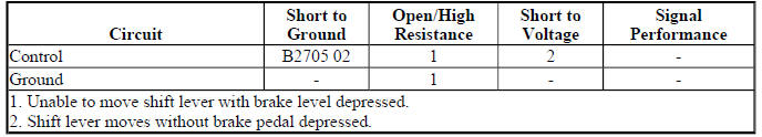
Diagnostic Fault Information
The fault information table should be used together with the wiring schematic and connector views. A short to ground can occur inside the harness, at a rubbed-through wire, inside a connector, at the shift lock solenoid, or in rare cases within the control module driver circuit. Testing should isolate the fault before any part is replaced.
Circuit/System Description
The body control module (BCM) controls the automatic transmission shift lock control solenoid by supplying battery positive voltage to the solenoid when release conditions are satisfied. The BCM uses a smart driver to control the voltage supply circuit. This smart driver is not only an output device; it also monitors voltage level and current flow in the controlled circuit.
When the driver presses the brake pedal with the ignition ON and the transmission in PARK, the BCM evaluates the required inputs and then commands the shift lock solenoid. If the circuit is healthy, the solenoid releases the mechanical lock and allows the shifter to move out of PARK. If the circuit is shorted to ground, the BCM detects abnormal current flow and sets DTC B2705 02.
On a Buick Enclave, this condition may show up as a shifter that will not move from PARK, a repeated shift lock complaint, or a stored body control module code found during scan tool diagnosis. The symptom may be constant or intermittent depending on the location and severity of the short.
Conditions for Running the DTC
The diagnostic runs only when the control module sees the correct operating conditions for shift lock release. These conditions allow the BCM to test the circuit while the system is expected to function.
- The ignition switch is in the ON position.
- The brake pedal is pressed.
- The transmission is in the PARK position.
Conditions for Setting the DTC
The DTC sets if the BCM detects a short to ground in the automatic transmission shift lock control solenoid control circuit. In practical terms, the module is seeing an electrical path to ground where it should not exist when the circuit is being commanded and monitored.
A short to ground may be caused by damaged insulation, a pinched harness, corrosion bridging terminals, an internal solenoid fault, water intrusion in a connector, or incorrect previous wiring repair. Because several causes can create the same DTC, the circuit must be tested step by step.
Action Taken When the DTC Sets
When DTC B2705 sets, the BCM will not attempt to enable the voltage supply circuit of the automatic transmission shift lock control solenoid until the next key cycle. This protects the smart driver and prevents repeated current overload on the affected circuit.
The driver may notice that the shifter remains locked in PARK even though the brake pedal is being pressed. If the concern is intermittent, cycling the ignition may temporarily restore operation, but the underlying circuit fault must still be located and repaired.
Conditions for Clearing the DTC
- A current DTC B2705 will clear when the malfunction is no longer present and the ignition switch is cycled.
- A history DTC will clear after 100 ignition cycles with no current DTC active during the 100 ignition cycles.
After repair, clearing the code alone is not enough. The shift lock command should be tested with a scan tool, the shifter release should be verified, and the brake pedal input should be checked to make sure the system responds normally.
Reference Information
Schematic Reference
Shift Lock Control Schematics
Connector End View Reference
COMPONENT CONNECTOR END VIEWS - INDEX
Description and Operation
Automatic Transmission Shift Lock Control Description and Operation
Electrical Information Reference
- Circuit Testing
- Connector Repairs
- Testing for Intermittent Conditions and Poor Connections
- Wiring Repairs
Scan Tool Reference
Control Module References for scan tool information
Use the reference information to identify the correct connector terminals, wire colors, circuit numbers, module locations, and scan tool output controls. For electrical faults, connector condition matters as much as the component itself. A loose terminal, spread pin, backed-out connector, or corrosion inside the harness can cause the same operating complaint as a failed solenoid.
Circuit/System Verification
1. Ignition ON, clear the DTC. Observe the scan tool BCM Stop Lamp Relay Command parameter while pressing and releasing the brake pedal. The parameter should change between ON and OFF.
- If the parameter does not change between the specified values, refer to Stop Lamps Malfunction. A brake input problem can prevent the shift lock system from releasing even when the solenoid and wiring are not the root cause.
2. Press the brake pedal, the vehicle operator should be able to move the shifter out of the PARK position.
If the shifter releases normally after the code is cleared and the brake input is verified, operate the system several times to check for an intermittent fault. Move the harness gently where accessible and watch for a repeat failure. Intermittent shift lock problems are often caused by wiring movement, connector tension, moisture, or a terminal that only loses contact under certain conditions.
Circuit/System Testing
1. Ignition OFF, disconnect the harness connector at the shift lock control solenoid.
Before testing, look closely at the solenoid connector and harness. Check for damaged locking tabs, terminal corrosion, loose pins, overheated plastic, water entry, stretched wiring, and any sign of rubbing against the console structure or nearby metal brackets.
2. Ignition OFF, test for less than 5.0 ohm between the ground circuit terminal B and ground.
- If greater than the specified range, test the ground circuit for an open/high resistance. A poor ground can prevent the solenoid from operating correctly and may create misleading symptoms during output testing.
3. Install a test lamp between the ground circuit terminal B and the control circuit terminal A.
Use a suitable test lamp for the circuit being checked. The lamp provides a simple load on the circuit and helps confirm that the BCM output can turn the solenoid control path on and off. Avoid using tools that may spread terminals or damage connector cavities.
4. Ignition ON, command the scan tool BCM Shift Lock Solenoid output control ON and OFF. The test lamp should turn ON and OFF as commanded.
- If the test lamp is always ON, test the control circuit for short to voltage. If the circuit tests normal, replace the BCM.
- If the test lamp is always OFF, test the control circuit for short to ground or an open/high resistance. If the circuit tests normal, replace the BCM.
If the lamp responds correctly, the control circuit is able to switch under scan tool command. At that point, test the shift lock solenoid itself and confirm that the mechanical shifter lock is not binding. A solenoid may receive the correct command but still fail to release the lock if the plunger sticks, the shifter mechanism is contaminated, or the console linkage is physically restricted.
After the circuit repair is completed, reconnect all components, clear the DTC, and perform a functional check. With the ignition ON and the brake pedal pressed, the shifter should release from PARK smoothly. With the brake pedal released, the selector should remain locked in PARK. This final check confirms that the electrical repair and the safety function are both working as intended on the Buick Enclave.
5. If the circuit checks good and no wiring, connector, ground, or control circuit fault is found, replace the transmission control only after the previous test results clearly support that decision. Module replacement should never be the first assumption in a shift lock concern, because poor terminal contact, harness damage, low system voltage, or an actuator fault can create the same symptom.
Repair Instructions
Perform the Diagnostic Repair Verification after completing the diagnostic procedure. Verification confirms that the original condition has been corrected and that the shift lock system operates correctly under the same conditions that produced the complaint. After repair, cycle the ignition, press and release the brake pedal several times, and confirm that the shifter releases from PARK only when the proper inputs are present.
- Automatic Transmission Shift Lock Control Actuator Replacement (Push-to-Release Style Solenoid) and Automatic Transmission Shift Lock Control Actuator Replacement (Pull-to-Release Style Solenoid)
- Control Module References for BCM replacement, setup and programming
When replacing the shift lock actuator, verify the style of solenoid before installation. A push-to-release design and a pull-to-release design may appear similar in the console area, but their mechanical action and mounting arrangement are different. Install the correct part, route the harness away from moving shifter components, and confirm that the connector is fully seated. If the BCM is replaced, complete the required setup, programming, and configuration steps before judging system operation.
SYMPTOMS - AUTOMATIC TRANSMISSION SHIFT LOCK CONTROL
IMPORTANT: The following steps must be completed before using the symptom tables.
1. Perform the Diagnostic System Check - Vehicle before using the Symptom Tables in order to verify that all of the following are true:
- There are no DTCs set.
- The control modules can communicate via the serial data link.
This preliminary check is important because a symptom table should not be used to chase a problem while active diagnostic trouble codes or communication faults are still present. If modules cannot communicate normally, or if related codes are stored, the shift lock complaint may be the result of a larger electrical or network issue rather than a failed shifter component.
2. Review the system operation in order to familiarize yourself with the system functions. Refer to Automatic Transmission Shift Lock Control Description and Operation.
Understanding the system before testing helps separate an actual malfunction from normal operating logic. The shift lock system is designed to hold the selector in PARK until the ignition state, brake pedal input, BCM command, solenoid operation, and mechanical release conditions are all correct. On a Buick Enclave, this system should be diagnosed as both an electrical circuit and a mechanical shifter release system.
Visual/Physical Inspection
- Inspect for aftermarket devices which could affect the operation of the automatic transmission shift lock control. Refer to Checking Aftermarket Accessories.
- Inspect the easily accessible or visible system components for obvious damage or conditions which could cause the symptom.
Look closely around the console, shifter assembly, brake pedal area, BCM-related wiring, and any location where previous repairs or accessories may have been installed. Remote starters, alarm systems, added wiring, damaged trim, spilled liquids near the shifter, or poorly routed harnesses can interfere with shift lock operation. A simple visual check can often reveal a pinched wire, loose connector, broken retaining clip, or contamination inside the shifter mechanism.
Intermittent
Faulty electrical connections or wiring may be the cause of intermittent conditions. Refer to Testing for Intermittent Conditions and Poor Connections.
Intermittent shift lock concerns can be difficult to duplicate because the system may work normally during the first inspection. Move the harness gently where accessible, watch scan tool data while pressing and releasing the brake pedal, and check for changes in solenoid command or circuit response. Pay attention to terminals that are loose, spread, corroded, backed out, or affected by moisture. A Buick Enclave with an intermittent PARK release complaint should be tested under the same conditions described by the driver whenever possible.
Symptom List
Refer to a symptom diagnostic procedure in order to diagnose the symptom:
Transmission Control Lever Malfunction
TRANSMISSION CONTROL LEVER MALFUNCTION
Diagnostic Instructions
- Perform the Diagnostic System Check - Vehicle prior to using this diagnostic procedure.
- Review Strategy Based Diagnosis for an overview of the diagnostic approach.
- Diagnostic Procedure Instructions provides an overview of each diagnostic category.
Use these diagnostic instructions to keep the repair process organized. The transmission control lever may fail to move from PARK because the solenoid is not being commanded, the brake input is missing, the ground path is poor, the control circuit is open or shorted, or the shifter mechanism itself is binding. Testing should prove which part of the system is failing before any component is replaced.
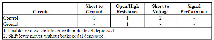
Diagnostic Fault Information
Circuit/System Description
The body control module (BCM) controls the shift lock solenoid by providing battery voltage to the shift lock control solenoid. The BCM uses a smart driver to control the voltage supplied to the solenoid. This smart driver also monitors voltage and current flow in the control circuit, allowing the module to recognize circuit behavior that is outside the expected range.
When the driver presses the brake pedal with the ignition ON and the transmission selector in PARK, the BCM evaluates the required inputs and commands the shift lock solenoid when release conditions are satisfied. If the circuit and actuator operate correctly, the shifter can be moved out of PARK. If the circuit has an open, excessive resistance, short to voltage, short to ground, or mechanical restriction, the selector may remain locked even though the brake pedal is being pressed.
Reference Information
Schematic Reference
Shift Lock Control Schematics
Connector End View Reference
COMPONENT CONNECTOR END VIEWS - INDEX
Description and Operation
Automatic Transmission Shift Lock Control Description and Operation
Electrical Information Reference
- Circuit Testing
- Connector Repairs
- Testing for Intermittent Conditions and Poor Connections
- Wiring Repairs
Scan Tool Reference
Control Module References for scan tool information
The reference information should be used to identify the correct connector cavities, terminal numbers, wire colors, scan tool controls, and module locations. Do not rely only on wire color when testing; confirm the circuit by the schematic and connector end view. This is especially important when previous repairs, aftermarket equipment, or harness damage may have altered the original wiring layout.
Circuit/System Verification
1. Ignition ON, clear the DTC. Observe the scan tool BCM Stop Lamp Relay Command parameter while pressing and releasing the brake pedal. The parameter should change between ON and OFF.
- If the parameter does not change between the specified values, refer to Stop Lamps Malfunction.
If the BCM does not recognize the brake pedal input, the shift lock release may not be commanded even when the solenoid and shifter assembly are capable of working. Confirm brake lamp operation, related fuses, stop lamp switch input, wiring condition, and scan tool data before continuing deeper into the shift lock circuit.
2. Press the brake pedal, the vehicle operator should be able to move the shifter out of the PARK position.
If the shifter releases normally, repeat the test several times and lightly move the accessible harness and connector areas while observing operation. If the shifter does not release, continue with circuit testing. On the Buick Enclave, the final judgment should be based on both scan tool data and actual shifter movement, not only on one test result.
Circuit/System Testing
1. Ignition OFF, disconnect the harness connector at the shift lock control solenoid.
Before using a meter or test lamp, inspect the connector at the solenoid. Check for damaged locking tabs, backed-out terminals, corrosion, bent pins, overheated plastic, water entry, or a connector that does not fully latch. Also check the shifter area for signs of spilled liquid or debris that could make the mechanical release stick.
2. Ignition OFF, test for less than 5.0 ohm between the ground circuit terminal B and ground.
- If greater than the specified range, test the ground circuit for an open/high resistance.
A high-resistance ground may allow some electrical activity but still prevent the solenoid from operating with enough force to release the shifter. If resistance is above the allowed range, repair the ground circuit, clean affected terminals where serviceable, and verify that the ground path remains stable while the harness is moved gently.
3. Install a test lamp between the ground circuit terminal B and the control circuit terminal A.
Use a suitable test lamp and avoid forcing the probe into the connector terminals. The purpose of this step is to place a simple load across the circuit so the BCM output command can be observed. If the lamp response is not correct, continue circuit testing before replacing the actuator or BCM.
4. Ignition ON, use the scan tool to command the BCM Shift Lock Solenoid output control ON and OFF. The test lamp should respond exactly with the command, turning ON when the output is commanded ON and turning OFF when the output is commanded OFF. This confirms that the control side of the circuit can be switched under load and that the BCM command is reaching the test point.
- If the test lamp remains ON at all times, check the control circuit for a short to voltage. If the wiring and connector terminals test correctly and no unwanted voltage feed is found, replace the BCM only after the circuit has been proven good.
- If the test lamp remains OFF at all times, check the control circuit for a short to ground, an open circuit, or high resistance. If the circuit, terminals, and related connections test normally, replace the BCM as directed by the diagnostic procedure.
5. If the circuit tests normal and the fault is still present, replace the transmission control only after confirming that the actuator, wiring, connector fit, ground path, and BCM command have all been checked correctly. This prevents unnecessary part replacement and keeps the repair based on verified test results.
Repair Instructions
Perform the Diagnostic Repair Verification after completing the diagnostic procedure. The repair should not be considered complete until the shift lock system operates normally, the diagnostic trouble code does not return, and the transmission selector releases from PARK only under the correct conditions.
- Automatic Transmission Shift Lock Control Actuator Replacement (Push-to-Release Style Solenoid) and Automatic Transmission Shift Lock Control Actuator Replacement (Pull-to-Release Style Solenoid)
- Control Module References for BCM replacement, setup and programming
Before replacing any actuator, identify which style of solenoid is installed. Push-to-release and pull-to-release actuators perform the same basic safety function, but their mechanical movement and mounting approach are different. Installing the wrong style can prevent the shifter from releasing or locking correctly. If a control module is replaced, complete all required setup, programming, and relearn procedures before final testing.
REPAIR INSTRUCTIONS
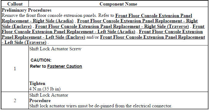
AUTOMATIC TRANSMISSION SHIFT LOCK CONTROL ACTUATOR REPLACEMENT (PUSH-TO-RELEASE STYLE SOLENOID)
The push-to-release shift lock actuator is part of the transmission selector locking system. Its job is to move the lock mechanism when the body control module supplies the proper command. When removing this actuator, keep the shifter area clean, avoid bending the linkage, and note the routing of the harness before disconnecting it. A small wiring misroute inside the console can create a repeat concern after the repair.
Fig. 2: Automatic Transmission Shift Lock Actuator
Automatic Transmission Shift Lock Control Actuator Replacement (Push-to-Release Style Solenoid)
During installation, make sure the actuator seats fully in its mounting position and that the release lever moves without binding. Reconnect the electrical connector until it locks securely. After the console trim is reassembled, test the shifter several times with the ignition ON and the brake pedal applied. The selector should move out of PARK smoothly, without sticking, dragging, or requiring excessive force.
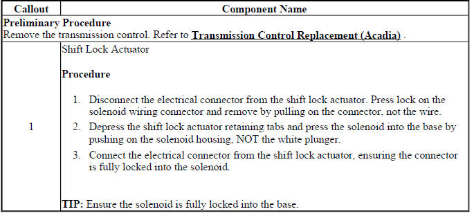
AUTOMATIC TRANSMISSION SHIFT LOCK CONTROL ACTUATOR REPLACEMENT (PULL-TO-RELEASE STYLE SOLENOID)
The pull-to-release style solenoid releases the shift lock by pulling the locking mechanism away from the selector path. Although the electrical purpose is similar to the push-style actuator, the mechanical action is different. Before removal, observe how the actuator engages the lock lever and how the harness is positioned. This makes installation cleaner and helps prevent a misaligned release mechanism.
Fig. 3: Automatic Transmission Shift Lock Control Actuator
Automatic Transmission Shift Lock Control Actuator Replacement (Pull-to-Release Style Solenoid)
When installing the pull-to-release actuator, confirm that the solenoid plunger has the correct travel and that it does not hold the lock partially released when de-energized. The selector must remain locked in PARK when the brake pedal is not applied, and it must release when the brake pedal is pressed with the ignition ON. For Buick Enclave service work, this final operational check is essential because the shift lock system is both a convenience feature and a safety device.
DESCRIPTION AND OPERATION
AUTOMATIC TRANSMISSION SHIFT LOCK CONTROL DESCRIPTION AND OPERATION
The automatic transmission shift lock control system is designed to prevent an unintended shift out of PARK. The driver must press the brake pedal before the shift lever can be moved from the PARK position. This prevents accidental selector movement when the vehicle is being started, parked, serviced, or left with the ignition on. The system works through a combination of mechanical locking parts, electrical control, brake pedal input, and module communication.
The system consists of the following components:
- The automatic transmission shift lock solenoid, serviced as the automatic transmission shift lock actuator, along with the body control module (BCM) and the engine control module (ECM). On vehicles equipped with a floor shifter, the shift lock solenoid is located within the floor shift control assembly.
- The BCM controls the voltage supply circuit for the shift lock control solenoid. Before the BCM supplies voltage, it must confirm that the required operating conditions are present.
The BCM controls voltage to the shift lock control solenoid through the controlled voltage circuit. The following conditions must be met before the BCM supplies voltage to the solenoid:
- The ignition is in the ON position.
- The ECM sends an input through GMLAN serial data to the BCM indicating that the transmission is in the PARK position.
- The BCM determines that the brake pedal is applied based on the brake pedal position input.
Since the shift lock control solenoid is permanently grounded, the BCM releases the system by supplying voltage to the actuator. When energized, the solenoid mechanically unlocks the shift lever and allows the driver to move the selector out of PARK. When the brake pedal is not applied, the BCM turns the controlled voltage output OFF. The solenoid de-energizes, and the locking mechanism holds the shift lever in the PARK position.
During remote start operation, the BCM keeps the shift lock control circuit de-energized so the shift lever remains locked in PARK. This prevents the vehicle from being shifted out of PARK during a remote start event before the driver has entered the vehicle and placed the ignition system in the correct operating state.
On the Buick Enclave, a shift lock complaint should be approached as a complete system issue rather than a single-part failure. Brake input, PARK status data, BCM output, actuator movement, connector condition, and mechanical shifter operation all need to match before the system will work correctly. A careful diagnosis avoids replacing the actuator when the real issue is a brake signal, wiring fault, module command problem, or mechanical restriction inside the shifter assembly.
