Buick Enclave: Description and Operation
BRAKE ASSIST SYSTEM DESCRIPTION AND OPERATION
System Component Description
The brake assist system is designed to reduce the amount of physical effort the driver must apply to the brake pedal while still allowing the hydraulic brake system to respond quickly and predictably. In the Buick Enclave, this system works together with the brake pedal, pushrod, vacuum brake booster, vacuum source, vacuum delivery components, and, when equipped, vacuum monitoring and control devices.
The brake assist system consists of the following:
Brake Pedal
The brake pedal receives the driver's input force, multiplies that force through pedal leverage, and transfers it into the brake assist and hydraulic brake system. Pedal condition, pivot movement, bushings, and return action all affect how the driver feels the brake system during normal stops and emergency braking.
Brake Pedal Pushrod
The brake pedal pushrod transfers the multiplied input force from the brake pedal to the brake booster. The pushrod must move smoothly and remain correctly aligned. Any binding, wear, looseness, or distortion can change pedal travel, pedal return, and the consistency of brake application.
Vacuum Brake Booster
The vacuum brake booster uses source vacuum to reduce the effort required by the driver when applying brake system input force. It does not replace the hydraulic brake system; instead, it assists the driver by using a pressure difference across one or more diaphragms inside the booster.
At rest, source vacuum is applied to both sides of the vacuum diaphragm for single boosters or to both sides of each diaphragm for tandem boosters. Return springs maintain the booster in a rest position until the driver applies the brake pedal.
When brake system input force is applied, vacuum to the rear side of the diaphragm or diaphragms is cut off, and atmospheric pressure is admitted in its place. The difference between vacuum on one side and atmospheric pressure on the other side helps move the booster diaphragm forward. This reduces the amount of pedal effort the driver must provide.
When input force is removed, vacuum again replaces atmospheric pressure inside the booster. The return springs and restored vacuum condition help the booster return to its rest position so the brake pedal can release normally.
Vacuum Source
The vacuum source supplies the vacuum used by the brake booster to decrease brake pedal effort. Without a stable vacuum supply, the brake pedal may become hard, braking may require noticeably more force, and the driver may experience inconsistent brake assist.
The primary source for vacuum is typically the vehicle's internal combustion engine. Some vehicles may also use a vacuum pump to maintain an adequate supply of vacuum under operating conditions where engine vacuum may be reduced, such as cold start-up, heavy throttle, high altitude, or changing engine load.
Vacuum Pump Relay
Vehicles equipped with a vacuum pump will typically use a relay to provide voltage to the vacuum pump motor when commanded by the powertrain controller. The relay allows the control system to activate the pump only when additional vacuum is needed for proper brake assist operation.
Vacuum Monitoring System
The vacuum monitoring system provides a feedback voltage signal related to the amount of vacuum available for the vacuum power brake booster. This information allows the vehicle control system to recognize when available vacuum is normal, low, or changing under different engine operating conditions.
This system typically consists of a vacuum sensor mounted into the power vacuum brake booster, integrated with the vacuum check valve, or installed in-line within the vacuum hose. The sensor feedback is usually monitored by the powertrain control module or related control modules.
Vacuum Source Control
If the vehicle is equipped with a system that monitors available vacuum levels for the brake assist system, the powertrain control module usually performs the primary monitoring function. It uses vacuum sensor input to help maintain brake assist availability during changing driving conditions.
The powertrain controller typically monitors the feedback signal from a vacuum sensor as it relates to available vacuum at the vacuum power brake booster. If the available vacuum drops below a predetermined level, the controller may reactivate engine cylinders if equipped, command a vacuum pump ON if equipped, or adjust other engine controls and devices as needed. This helps ensure the Buick Enclave can maintain proper brake assist even when engine vacuum demand changes.
Vacuum Source Delivery System
The vacuum source delivery system enables delivery and retention of vacuum for the vacuum brake booster. It usually includes a vacuum check valve and a vacuum hose or pipe. If a vacuum pump is used, additional check valves may be included to control vacuum direction and prevent loss of stored assist.
The check valve is especially important because it helps hold vacuum in the booster when engine vacuum decreases or when the engine is shut off. A leaking hose, cracked fitting, loose connection, or faulty check valve can reduce assist and may cause the brake pedal to feel harder than normal.
System Operation
Brake system input force from the driver is multiplied by the brake pedal and transferred by the pedal pushrod to the hydraulic brake master cylinder. The effort required to apply the brake system is reduced by the operation of the vacuum brake booster.
When brake system force is applied, vacuum to the rear of the diaphragm or diaphragms is cut off, and atmospheric pressure is admitted in its place. Vacuum acts to pull the diaphragm forward, while atmospheric pressure acts to push from behind. As a result, the driver does not need to apply as much force to achieve the required brake system response.
When the driver removes input force from the brake pedal, vacuum again replaces atmospheric pressure inside the vacuum power brake booster. This helps the booster return to its rest condition, while the return springs maintain the system in the correct released position.
If the vehicle is equipped with a vacuum monitoring system, the powertrain control module typically alters powertrain functions and/or commands the vacuum pump ON, if equipped, to provide the vacuum needs of the brake assist system as operating conditions require. This coordinated operation helps maintain stable brake pedal effort and predictable brake feel on the Buick Enclave.
BRAKE WARNING SYSTEM DESCRIPTION AND OPERATION
Brake Warning Indicator
Hydraulic Brakes Block Diagram
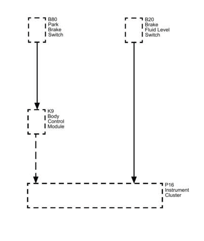
Fig. 67: Hydraulic Brakes Block Diagram

The brake warning system informs the driver when certain brake-related conditions are detected. The red brake warning indicator should always be taken seriously because it may be related to the park brake, brake fluid level, ABS-related brake force distribution, communication faults, or the normal bulb check during ignition start-up.
The instrument panel cluster (IPC) illuminates the Red Brake Warning indicator when one or more of the following occurs.
- The body control module (BCM) detects that the park brake is engaged.
- The IPC detects a low brake fluid condition. The IPC receives a low brake fluid signal from the low brake fluid switch in the master cylinder reservoir requesting illumination.
- The electronic brake control module (EBCM) detects an ABS malfunction which disables dynamic rear proportioning (DRP). The IPC receives a GMLAN message from the EBCM requesting illumination.
- The IPC performs the bulb check at the start of each ignition cycle. The Red Brake Warning indicator illuminates for approximately 3 seconds before turning OFF.
- The IPC detects a loss of GMLAN communications with the EBCM.
During normal operation, the warning indicator may illuminate briefly as part of the bulb check. However, if the indicator remains illuminated after the initial check, the brake system should be inspected before the vehicle is driven further. A low brake fluid condition, active park brake signal, disabled dynamic rear proportioning, or lost communication with the EBCM can affect brake system safety and driver confidence.
HYDRAULIC BRAKE SYSTEM DESCRIPTION AND OPERATION
System Component Description
The hydraulic brake system converts driver input into controlled braking force at the wheels. It depends on clean brake fluid, sealed hydraulic circuits, properly routed pipes and hoses, and wheel-end components that can convert hydraulic pressure into mechanical clamping force. In the Buick Enclave, hydraulic pressure distribution and brake force control are also supported by ABS-related functions where equipped.
The hydraulic brake system consists of the following:
Hydraulic Brake Master Cylinder Fluid Reservoir
The hydraulic brake master cylinder fluid reservoir contains the supply of brake fluid for the hydraulic brake system. It allows the system to compensate for brake lining wear and provides fluid volume for normal hydraulic operation. The reservoir must remain clean, sealed, and filled with the correct brake fluid.
Hydraulic Brake Master Cylinder
The hydraulic brake master cylinder converts mechanical input force into hydraulic output pressure. When the driver applies the brake pedal, the master cylinder pressurizes the brake fluid and sends that pressure through the hydraulic circuits.
Hydraulic output pressure is distributed from the master cylinder through 2 hydraulic circuits, supplying diagonally opposed wheel apply circuits. This circuit design helps preserve partial braking ability if one hydraulic circuit develops a fault, although any hydraulic problem must still be repaired immediately.
Hydraulic Brake Pressure Balance Control System
The hydraulic brake pressure balance control system regulates brake fluid pressure delivered to the hydraulic brake wheel circuits in order to control the distribution of braking force. Proper pressure balance helps the vehicle remain stable during braking and reduces the chance of excessive rear wheel brake force.
Pressure balance control is achieved through dynamic rear proportioning (DRP), which is a function of the ABS modulator. Refer to ABS Description and Operation for specific information on the operation of DRP.
Hydraulic Brake Pipes and Flexible Brake Hoses
Hydraulic brake pipes and flexible brake hoses carry brake fluid to and from hydraulic brake system components. Brake pipes provide rigid routing through the vehicle structure, while flexible hoses allow movement at the wheels and suspension. Both must remain free of leaks, kinks, corrosion, twisting, and internal restrictions.
Hydraulic Brake Wheel Apply Components
Hydraulic brake wheel apply components convert hydraulic input pressure into mechanical output force. At the wheel ends, this force presses the friction material against rotating brake components to slow or stop the vehicle. If the apply components bind, leak, wear unevenly, or fail to release, the driver may notice brake drag, noise, pulling, overheating, or abnormal pedal feel.
System Operation
Mechanical force is converted into hydraulic pressure by the master cylinder, regulated to meet braking system demands by the pressure balance control system, and delivered to the hydraulic brake wheel circuits by the pipes and flexible hoses. The wheel apply components then convert hydraulic pressure back into mechanical force, pressing the linings against rotating brake system components.
In normal operation, the system should build pressure quickly, hold that pressure without leakage, and release cleanly when the brake pedal is released. Any spongy pedal, excessive travel, brake warning indicator, fluid loss, uneven braking, or delayed brake release should be diagnosed before the Buick Enclave is returned to service.
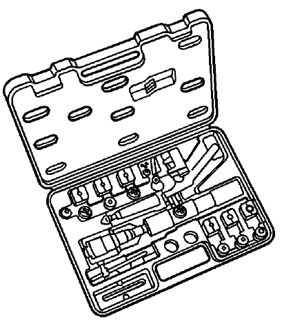
SPECIAL TOOLS AND EQUIPMENT
SPECIAL TOOLS
Special tools help measure brake pedal effort, bleed the hydraulic system, adapt pressure bleeding equipment to the reservoir, and form brake pipe flares accurately. Using the correct tool reduces the risk of incorrect measurements, poor bleeding results, damaged fittings, or unsafe brake pipe repairs.
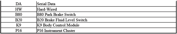
J 28662
Brake Pedal
Effort
Gauge
The J 28662 Brake Pedal Effort Gauge is used when brake pedal force must be measured during inspection or diagnosis. It helps confirm pedal travel and brake response under a known applied force instead of relying only on subjective pedal feel.
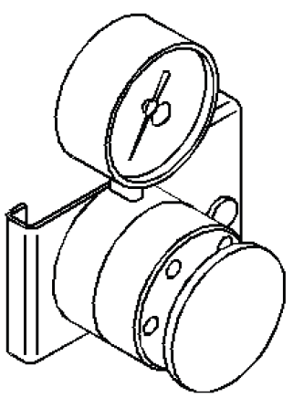
J 29532
Diaphragm
Pressure
Bleeder
The J 29532 Diaphragm Pressure Bleeder supplies clean brake fluid under controlled pressure. The diaphragm design separates the air supply from the brake fluid, helping prevent moisture, oil, and other contaminants from entering the hydraulic brake system during bleeding.
J 44894-A
Brake
Pressure
Bleeder
Adapter
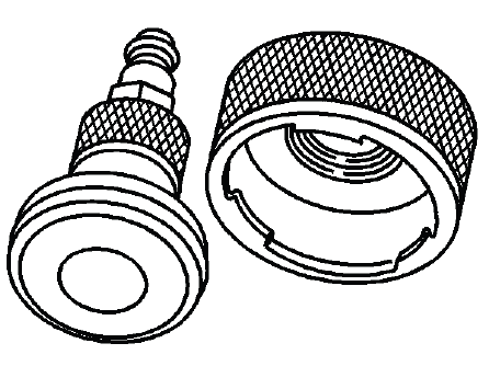
The J 44894-A Brake Pressure Bleeder Adapter connects pressure bleeding equipment to the master cylinder reservoir. A proper adapter seal is required to maintain pressure and prevent fluid leakage while the hydraulic brake system is being serviced.
J 45405
Brake Pipe
Flaring Kit
The J 45405 Brake Pipe Flaring Kit is used to prepare and form replacement brake pipe flares that match the original design. Correct flare shape, pipe diameter, fitting type, and surface finish are critical because brake pipe connections must seal under high hydraulic pressure without leaking.
